Comtech EF Data SDM-9000 User Manual
Page 160
Maintenance
SDM-9000 Satellite Modem
6–2
Rev. 4
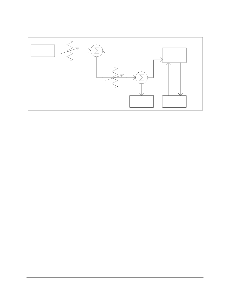
VAR ATTEN
NOISE
GENERATOR
TX IF
MODEM
UNDER
TEST
RX IF
VAR ATTEN
DATA
CONNECTORS
BER
SPECTRUM
ANALYZER
TEST SET
Figure 6-1. Fault Isolation Test Setup
1. Ensure the interface is configured for the proper mode of operation. Refer to
Chapter 3 for configuration jumper settings.
2. Connect a BER test set to the appropriate modem data connector as shown in
Figure 6-1. Refer to Chapter 2 for the following data connections:
a.
MIL-STD-188
b. G.703
c.
ECL
d. PECL
3. Set up the modem for baseband loopback operation by using the Configuration
Interface front panel menu (refer to Chapter 4). The test set should run error free.
Refer to Figure 4-19 for a block diagram of the baseband loopback operation.
4. Change the modem from baseband loopback to interface loopback operation by
using the Configuration Interface front panel menu (refer to Chapter 4). The test
set should run error free. Refer to Chapter 4 for a block diagram of the interface
loopback operation.