Comtech EF Data SDM-9000 User Manual
Page 60
Configuration
SDM-9000 Satellite Modem
3–2
Rev. 4
JP2
JP3
JP1
JP5
JP9
JP10
ASSEMBLY NUMBER AND
SERIAL NUMBER
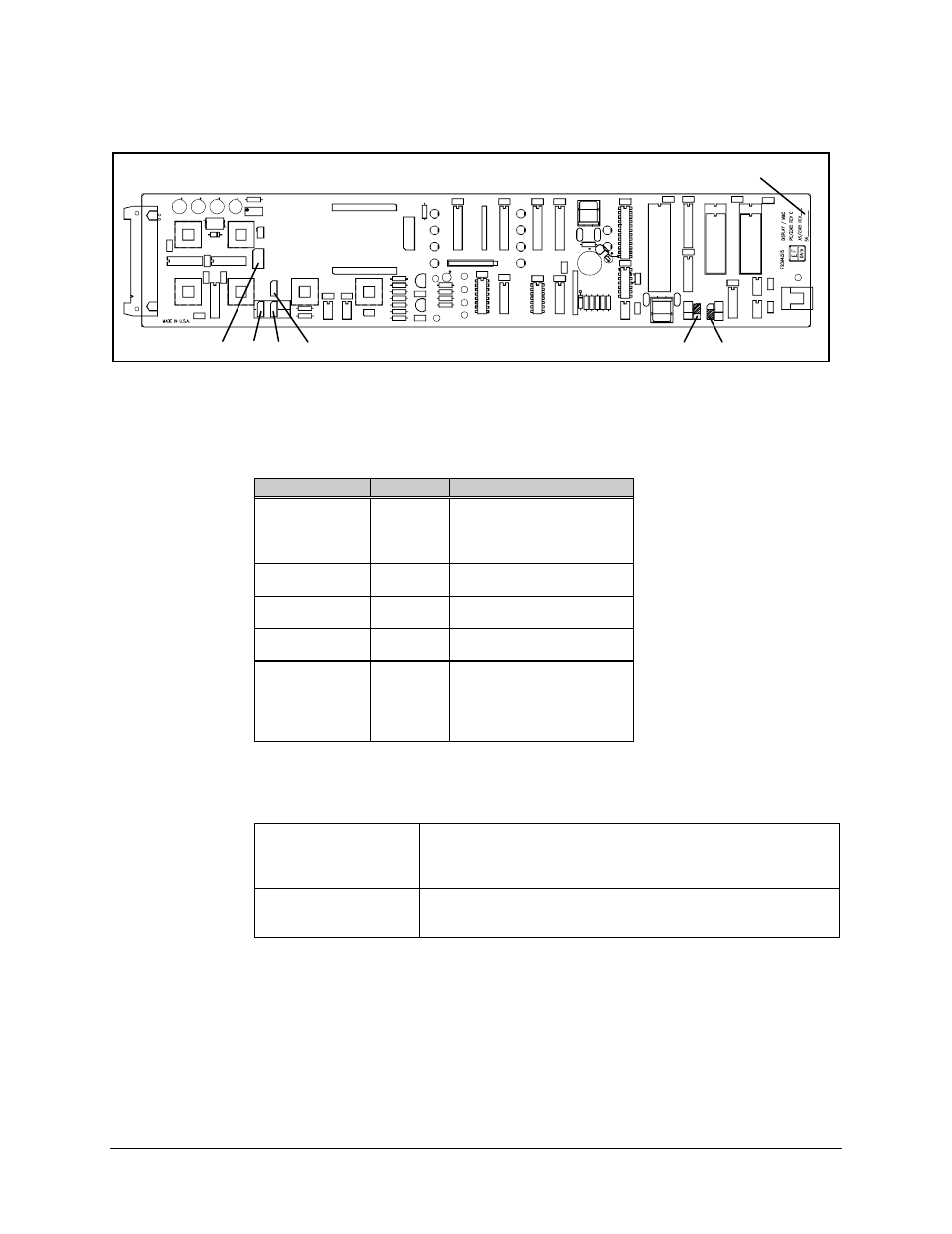
Figure 3-1. Display/M&C PCB
Table 3-1. Display/M&C PCB Jumper Settings
Jumper
Position
Function
JP1
1 to 2
3 to 4
5 to 6
7 to 8
RS-485 Remote
RS-485 Remote
RS-232-C Remote
RS-232-C Remote
JP2
(See Note
)
1 to 2
2 to 3
4-Wire
2-Wire
JP3
(See Note)
1 to 2
2 to 3
4-Wire
2-Wire
JP5
1 to 2
2 to 3
RS-485 Remote
RS-232-C Remote
JP9 and JP10
32K
64K
128K
256K
256K
27C256 EEPROM at U17
27C512 EEPROM at U17
27C010 EEPROM at U17
27C020 EEPROM at U17
27C040 EEPROM at U17
Note: Pins JP2 and JP3 must be in the 4-wire position for RS-232-C.
RS-485 Configuration
Install two jumpers (shunts) at the RS-485 positions of JP1, and
install one jumper at the RS-485 position of JP5.
For 2- or 4-wire operation, position jumpers at JP2 and JP3 to the
designated positions.
RS-232-C Configuration
Install two jumpers (shunts) at the RS-232-C positions of JP1, and
install one jumper at the RS-232-C position of JP5.
Install jumpers at JP2 and JP3 for 4-wire operation.