2 description – Comtech EF Data SDM-9000 User Manual
Page 26
Introduction
SDM-9000 Satellite Modem
1–4
Rev. 4
1.1.2 Description
The modem is a complete, self-contained unit in a standard 2 unit (2U) 19”
rack-mountable enclosure weighing approximately 19 lbs. The unit is of modular
construction consisting of five PCB assemblies:
•
Modulator
•
Demodulator
•
Interface
•
Display/Monitor & Control (M&C) (front panel)
•
Backplane (rear panel)
The backplane PCB is mounted on the chassis assembly and contains receptacles for
three plug-in PCBs:
•
Modulator
•
Demodulator
•
Interface
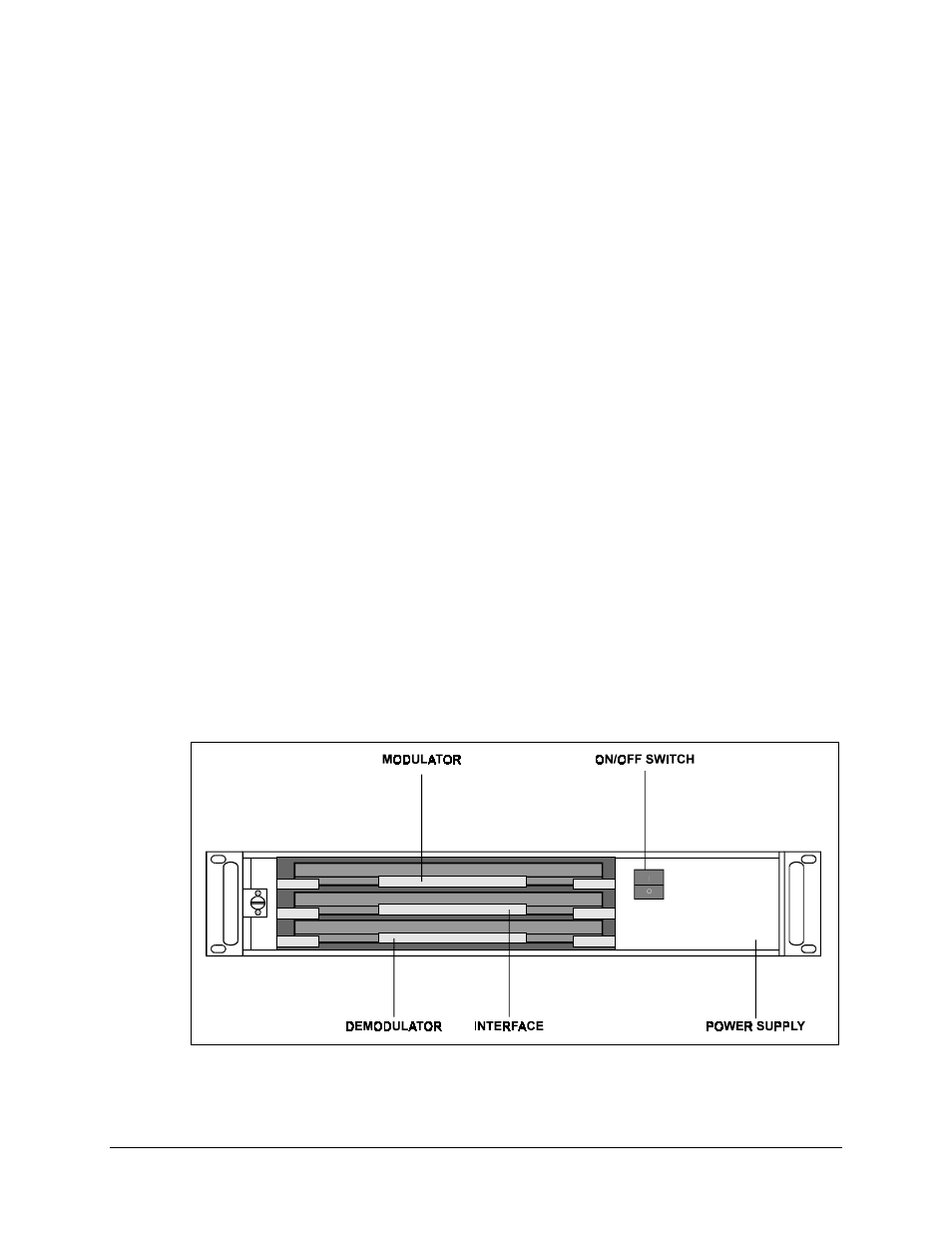
Test points are located on the front edges of the three PCBs. Figure 1-2 shows the front
view of the modem (without the front panel).
All M&C functions and indicators for operation of the modem are located on the
display/M&C. The chassis also contains a fan (on the rear panel) and a power supply.
Refer to Figure 1-3 for a system block diagram.
Figure 1-2. Modular Construction