9 aux 1 (j9) – Comtech EF Data SDM-9000 User Manual
Page 56
Installation
SDM-9000 Satellite Modem
2–14
Rev. 4
2.4.9 AUX 1 (J9)
The Auxiliary 1 (AUX 1) connector provides:
•
TTL faults
•
External high stability reference
•
AGC output voltage
The faults are open collector levels to indicate a modulator or demodulator failure. A
logic 1 indicates the faulted condition. The signals are primarily used in operating a
protection switch.
The external high stability reference clock input is 5, 10, or 20 MHz.
AGC-OUT is the voltage for a receive signal level between -25 and -50 dBm.
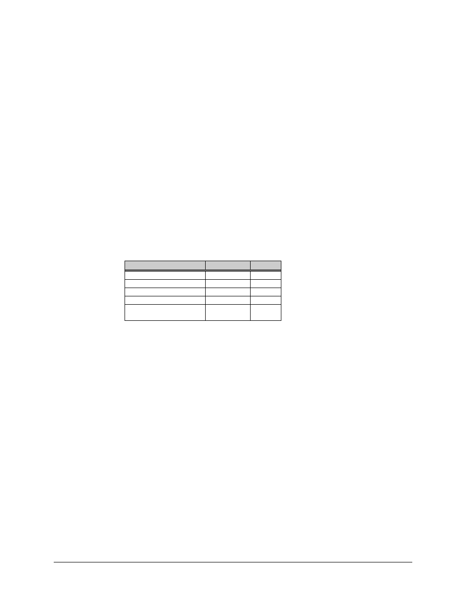
The AUX 1 connection is a 9-pin female D connector located on the rear panel of the
modem. Screw locks are provided for mechanical security on the mating connector.
Signal Function
Name
Pin #
Ground
GND
5, 6, 8
External reference
EXT–REF
2
Transmit fault
MDTTLFLT
4
Receive fault
DMTTLFLT
7
AGC output
(Receive input, IF level)
AGC–OUT
1