A.2.2 baseband physical interfaces, A.2.2.1 ecl physical interface – Comtech EF Data SDM-9000 User Manual
Page 198
Options
SDM-9000 Satellite Modem
A–12
Rev. 4
A.2.2 Baseband Physical Interfaces
The baseband physical interface for the DBS mode is provided by the Emitter Coupled
Logic (ECL) or Positive Emitter Coupled Logic (PECL) interface boards installed in the
SDM-9000. Refer to Sections A.2.2.1 and A.2.2.2 for information about the respective
interface boards.
Characteristics of the baseband physical interface are described in Section A.2.3.
Timing requirements for the baseband physical interface are presented in Section A.2.4.
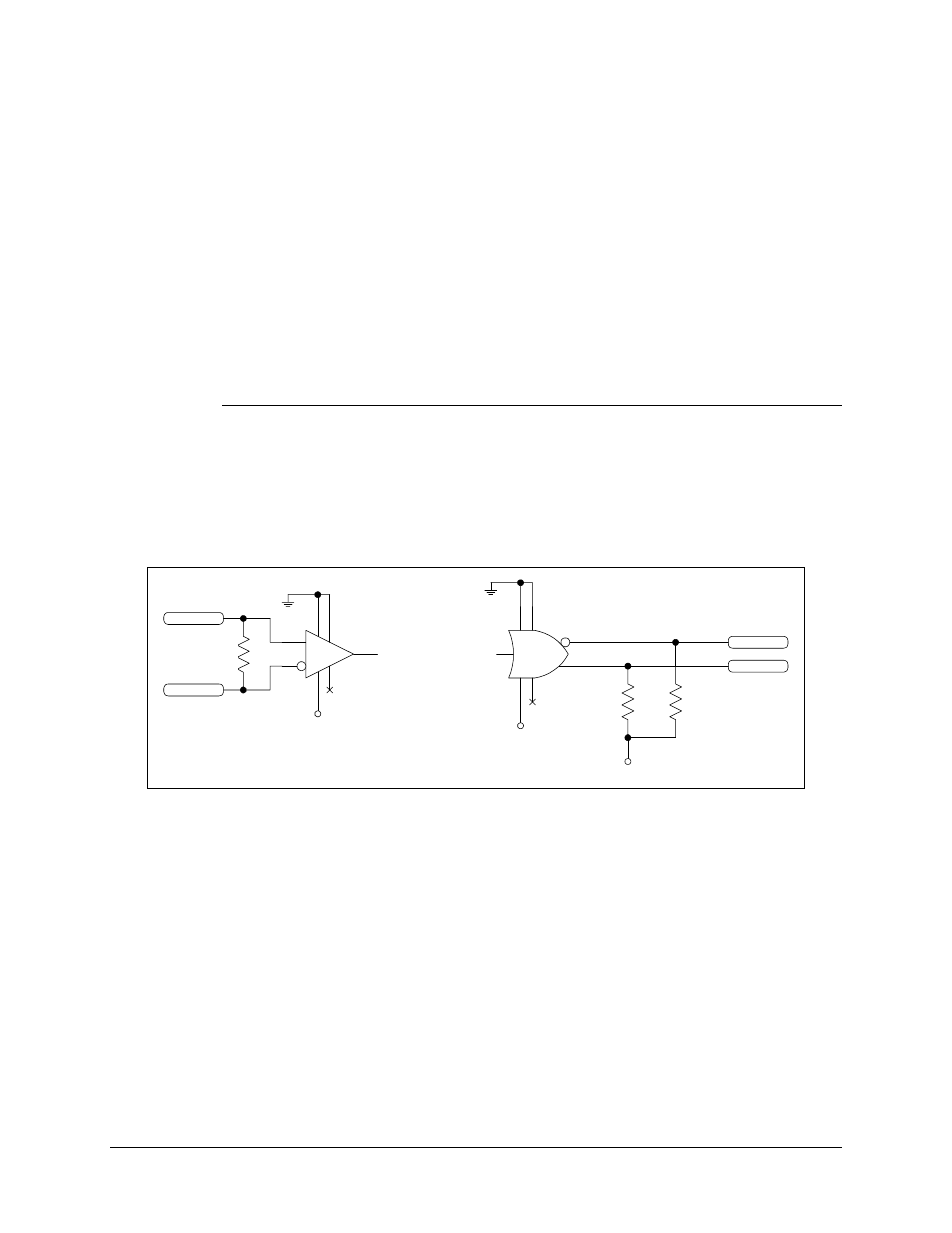
A.2.2.1 ECL Physical Interface
The ECL interface uses MC10H115 differential line receivers and MC10H101
differential line drivers to provide the electrical interface to the SDM-9000. Figure A-7
shows a typical differential ECL receiver and driver diagram.
5
2
1
16
8
12
4
MC10H101
5
4
2
1
16
8
9
MC10H115
100
+ECL_IN
-ECL_IN
-5.2V
-5.2V
330
-ECL_OUT
+ECL_OUT
330
-5.2V
Figure A-7. Typical Differential ECL Receiver and Driver