Installing the rotation handle – DR Power 30 Snow Thrower User Manual
Page 18
14 DR
®
SNOW THROWER ATTACHMENT
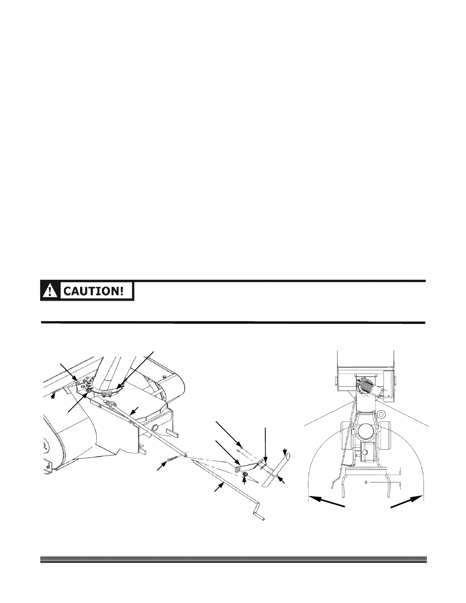
Installing the Rotation Handle
Tools Needed:
•
7/16" Wrench or Socket
•
Pliers
1. Using a 7/16" Wrench or Socket, install the Rotation Handle Support (Figure 9) on the left side
Handle Bar of your DR FIELD and BRUSH MOWER approximately 28" from the ground using the
U-Bolt, Plate and Nuts.
2. Insert the Plastic Bushing, with the flange facing the operator, into the Snow Thrower Housing by
pushing the Bushing forward until it snaps into place (Figure 9).
3. Insert the Worm Gear end of the Rotation Shaft in the Plastic Bushing and engage the Worm Gear
with the gear teeth on the Discharge Chute Flange (Figure 9).
4. Place the Flat Washer over the end of the Worm Shaft and insert the Cotter Pin (Figure 9). Spread
the ends of the Cotter Pin with the pliers to hold the Pin in place.
5. Insert another Plastic Bushing, with the flange facing the operator, into the Rotation Handle
Support by pushing the Bushing forward until it snaps into place
(
Figure 9
).
6. Insert the Handle of the Rotation Shaft through the Bushing in the Rotation Handle Support and
then into end of the Worm Gear Shaft (Figure 9).
7. Secure the two halves of the Rotation Shaft together by aligning the holes in the shaft ends and
inserting a Hairpin Clip (Figure 9).
8. Operate the Rotation Handle and check that the Discharge Chute rotates smoothly.
MAKE SURE THE DISCHARGE CHUTE STOPS IN BOTH DIRECTIONS TO PREVENT SNOW FROM
DISCHARGING IN THE OPERATOR ZONE (
FIGURE 10).
Hazard
Zone
Hazard
Zone
Operator Zone
31" Radius
4"
Figure 10
Mower Left
Handlebar
Support
Plate
Bushing
U-Bolt
Rotation Handle
Hairpin Clip
Nut (2 pls.)
Worm
Gear Shaft
Bushing
Cotter
Pin
Washer
Figure 9
Discharge Chute Flange
Snow Thrower
Housing