DR Power Self-Propelled Pro-XL Self-Propelled 8.26fpt Subaru User Manual
Page 18
18
DR
®
TRIMMER/MOWER
Always make sure you remove the screwdriver from the head assembly when
finished. Failure to remove the screwdriver could cause injury when the head
assembly is engaged.
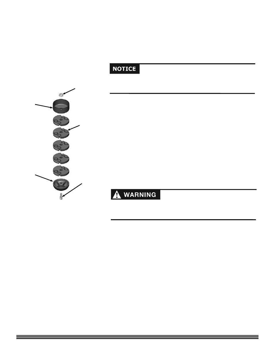
4. Looking down at the top of the Frame, turn the Mow-Ball
®
clockwise until it unscrews completely from the Bearing Housing.
Note: If the Mow-Ball
®
continues to turn, but does not come off, check to be sure that you locked the Screwdriver into the shaft.
If the Mow-Ball will not turn by hand a 9/16" Socket can be used on the Bolt (inside the bottom of the Mow-Ball) to loosen it.
You may need to clean grass or debris out of the recess first.
5. Slide the Line Plates off the Shaft.
6. Place the Spacer and Anti Wrap Canister (with the lip facing up) onto the
Shaft (Figure 24).
7. Align the flats at the center of the Plates with the flat on the shaft and slide
the Line Plates onto the Shaft. Ensure they are facing top side up as shown.
8. Place the head of the Mow-Ball
®
Bolt so it is sitting in the hex cavity at the
bottom of the Mow-Ball
®
.
9. Looking down at the top of the Frame, hold the Bolt Head in place with your
finger and turn the Mow-Ball
®
counterclockwise to start the Bolt into the
Shaft.
10. Tighten the assembly securely by turning the Mow-Ball
®
counterclockwise
when looking down on the top of the Frame.
11. Remove the Screwdriver.
Note: When finished there should be no gaps between any of the components.
Figure 24
Spacer
Line Plates
Anti Wrap
Canister
Mow-Ball
®
Mow-Ball
®
Bolt
Improper installation can cause damage to the trimmer bearings. Follow
these directions carefully to protect your machine from damage. Reassemble
the components in the order shown in figure 24.