Blower exit elbow assembly installation – DR Power Tow-Behind 8.00 Premier (Pre-August 2010) User Manual
Page 22
18 DR
®
PREMIER LEAF and LAWN VACUUM
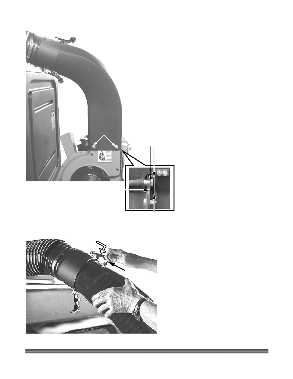
1. Install the Blower Exit Elbow Assembly
on top of the Blower with the Elbow
pointing toward the Collector Box
(Figure 10).
2. Align the Hood of the Blower Exit Elbow
Assembly to ensure that the Safety
Interlock Switch is engaged, and then
install a Lock Washer and Flat Washer
over each of the four (4) 5/16" x 1/2"
Wing Screws and hand tighten them to
the Blower Housing (Figure 10).
Tip: Start all four (4) Wing Screws before
tightening them securely.
NOTE: If the Safety Interlock Switch is not
engaged (Button fully depressed), the
Engine will not start. If the distance
between the Contact Bracket and
Safety Switch Bracket is greater than
1/4", remove the Blower Exit Elbow
Assembly and bend the Contact
Bracket to achieve the proper
dimension (Figure 10).
Blower Exit Elbow Assembly Installation
The following procedure includes the steps
necessary for installing the Blower Exit Elbow
Assembly on the DR LEAF and LAWN
VACUUM.
Connecting the Collector Box Inlet Hose to
the Blower Exit Elbow Assembly
The following procedure includes the steps
necessary for connecting the Collector Box
Inlet Hose to the Blower Exit Elbow Assembly
on the DR LEAF and LAWN VACUUM.
Blower Exit Elbow
Pull and Hook
Flexible Latches
Collector Box Hose
Hook here
Figure 11
Figure 10
Collector Box
Hose
Safety Interlock
Switch Bracket
Wing Screw
(4 places)
Blower Exit Elbow
Assembly
1. Connect the Hose from the Collector
Box to the Blower Exit Elbow Assembly
by aligning the two (2) Flexible Latches
(Figure 11) and slipping the Hoses
together.
2. Pull and hook the two (2) Flexible
Latches into place (Figure 11) to secure
the Hoses.
Blower Housing
Contact Bracket
1/4"
Maximum