Removing and replacing the chipper knife – DR Power Tow-Behind 8.00 Premier (Pre-August 2010) User Manual
Page 45
CONTACT US AT
www.DRPower.com
or CALL TOLL FREE 1-800-DR-OWNER 41
Wing Nut
4-pls.
Removing and Replacing the Chipper Knife
ROUTINELY CHECK THE CHIPPER KNIFE FOR SHARPNESS. USING A DULL KNIFE
WILL DECREASE PERFORMANCE AND CAUSE EXCESSIVE VIBRATION THAT WILL CAUSE DAMAGE TO THE
CHIPPER ENGINE. IF YOU WISH TO SHARPEN THE KNIFE, SEE THE NEXT PAGE FOR INSTRUCTIONS.
WHEN PERFORMING ANY MAINTENANCE, YOU MUST FIRST SHUT OFF THE
ENGINE, WAIT FIVE (5) MINUTES FOR PARTS TO COOL AND DISCONNECT THE SPARK PLUG WIRE.
Tools Needed:
•
(2) 1/2" Wrench or Socket
•
9/16" Wrench or Socket
•
3/16" Allen Wrench
•
Anti-Seize Compound
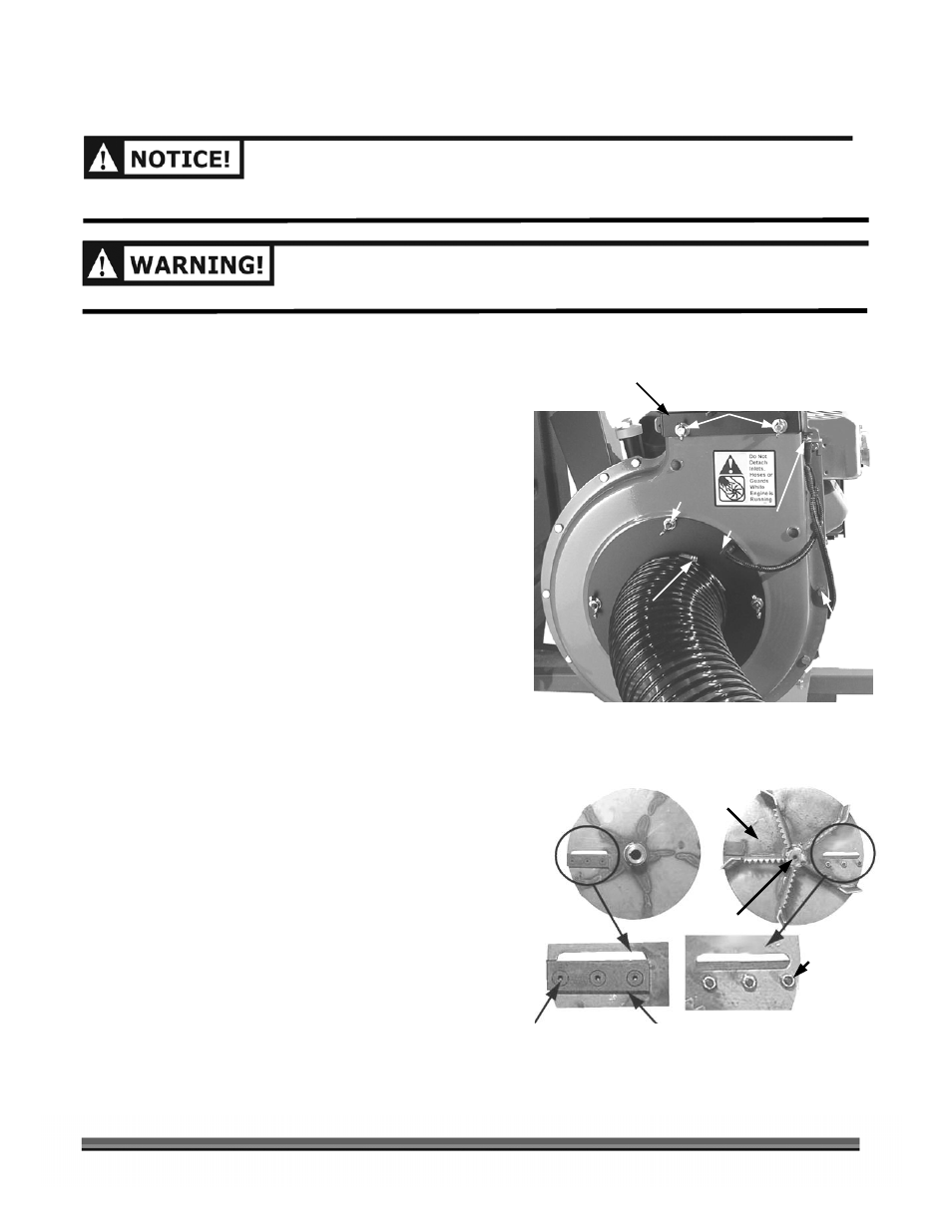
Figure 35
Figure 36
Nylon
Nut
Chipper Knife
Allen Head
Screw
Chipper
Impeller
Bolt
Wing Screw, 4 - places
Inlet Hose
Adapter
Bolt and
Nut,
12 - places
Blower
Cover
Plate
Back Front
Hose
Clamp
1. Disconnect the Blower Exit Elbow Assembly from
the Collector Box Hose (Figure 34).
2. Remove the Wing Nuts and Wing Screws to
disconnect the Inlet Hose Adapter and Blower Exit
Elbow Assembly from the Chipper/Blower unit
(Figure 35).
3. Using two (2) 1/2" Wrenches or Sockets, remove
the twelve (12) Bolts and Nuts retaining the Blower
Cover Plate (Figure 35) and remove the Plate from
the Blower Housing. The Chipper Impeller is now
exposed.
4. Using a 9/16" Wrench or Socket, remove the
Chipper Impeller retaining Bolt (Figure 36) from the
Engine shaft and slide the Impeller off the shaft. Be
sure to save the Key in the slotted shaft.
5. The Chipper Knife is attached to the Impeller with
three (3) Allen head screws and three (3) nylon Lock
Nuts (Figure 36). Using a 3/16" Allen Wrench and
1/2" Wrench, remove the old Chipper Knife by
removing the three (3) Screws and Nuts.
NOTE: Carefully observe the orientation of the Chipper
Knife edge and mounting holes when removing the
Knife.
6. Install a new or sharpened Chipper Knife and
Impeller in the reverse order making sure to install
the Key in the Engine shaft keyway. Coat the Engine
crankshaft with Anti-Seize Compound to protect
surfaces.
NOTE:
If the Safety Interlock Switch is not engaged
(Button fully depressed), the Engine will not start.
See page 18.
Wing Nut
4 pls.
Safety Interlock
Switches
Blower Exit Elbow
Assembly