Description of quatafire 610, 1 front panel, 1) power switch and power led – ESI QuataFire 610 User Manual
Page 4: 2) channel 1/2 input connectors, 3) channel 1/2 gain controls, 4) +48v phantom power switch, 5) line/mic selection switch
ESI QuataFire
610
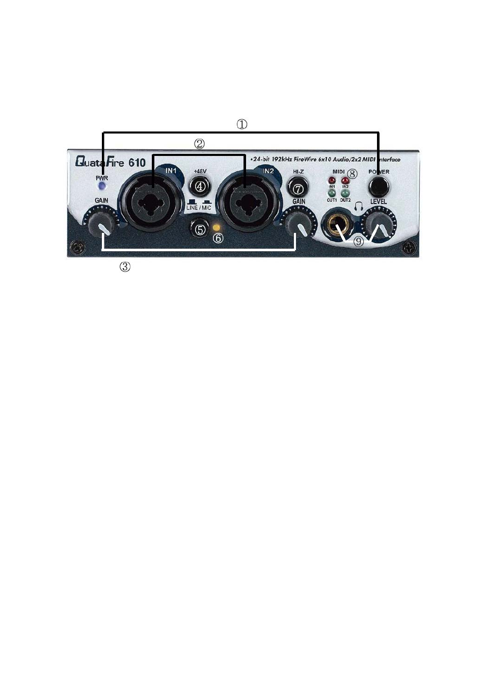
4. Description of QuataFire 610
1 Front Panel
(1) Power Switch and Power LED:
a. Green:
Green PWR LED indicates that QuataFire 610 is functioning
normally.
b. Red and blinking:
Red and blinking LED indicates:
·
QuataFire 610 is initializing
·
QuataFire 610 is detecting external clock source when
S/PDIF input is connected to another device.
c. Green and blinking:
Green and blinking LED indicates QuataFire 610 is in
abnormal status. Please click “Factory Default” in the control
panel to initialize the hardware.
(2) Channel 1/2 input connectors:
Balanced XLR/TRS universal (combo) connectors.
(3) Channel 1/2 gain controls:
Control input level of each microphone or line input (for both XLS and TRS).
(4) +48V phantom power switch:
Supply 48V DC phantom power to input channels 1/2 simultaneously by pressing the
button.
(5) LINE/MIC selection switch:
Pressed:
Input 1/2 used for microphone signals
Depressed:
Input 1/2 used for line level signals
4