5 piping – Flowserve Worthington WXB User Manual
Page 15
WXB USER INSTRUCTIONS ENGLISH - 07/14
Page 15 of 51
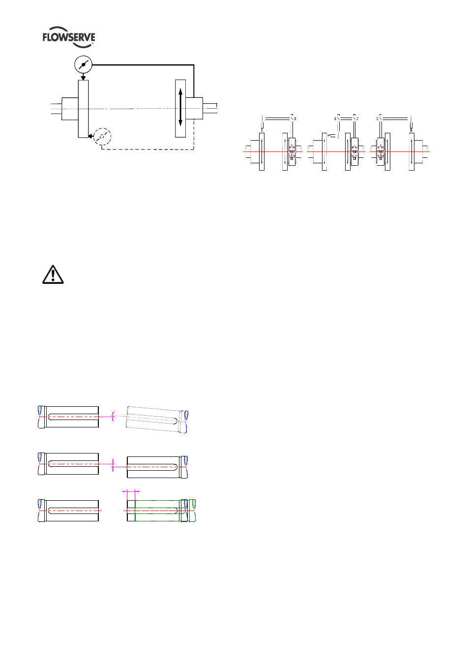
Parallel
Angular
Ensure pump and driver are isolated electrically and
the half couplings are disconnected.
Align the motor to the pump, not the pump to the
motor. Alignment of the motor is achieved by using
the adjustment screws.
4.4.1 Permissible misalignment limits at working
temperature
When checking parallel alignment, the total indicator
read-out (TIR) shown is twice the value of the actual
shaft displacement.
The pump is only pre-aligned! Carefully check
or read just alignment before start of the unit.
Take out the spacer of the coupling and check the
alignment of shafts end of pump and driver. The
maximum allowable angular offset should not exceed
0,05 degree, this means the alignment of the shaft
ends should be 0,1 mm (0.004 in.). The maximum
parallel offset should not exceed 0,05 mm
(0.002 in) and the axially offset can be ± 1 mm (0.04
in.).
For more details refer to the manufacturer’s
instruction manual of coupling.
a)
b)
c)
a) Angular Offset:The median lines of shafts
intersect half-way between the ends of the two
shafts.
b) Parallel Offset: The median lines run parallel. The
maximum allowable parallel offset depends on
the size of coupling and is indicated in the
instruction manual of manufacturer of coupling
c) Axially Offset: Another offset is the displacement
of one or both of the shafts. A typical example is
thermal expansion.
How the alignment of the coupling should be done
you can see on the sketches and explanations below!
a)
b)
c)
a) Fix the dial gauge on the driven shaft and check
the concentricity by turning of both hubs; correct it if
necessary.
b) Fix the dial gauge on one of the hubs and check
the uniformity of the distance by turning of both
hubs.; correct it if necessary.
c) Fix the dial gauge on the driving shaft and check
the concentricity by turning of both hubs; correct it if
necessary.
If the pump is handling hot liquid, the alignment must
be rechecked in warm condition of the unit.
4.5 Piping
4.5.1 General
Protective covers are fitted to the pipe connections to
prevent foreign particles entering during
transportation and installation. Ensure that these
covers are removed from the pump before connecting
any pipes.
Maximum forces and moments allowed on the pump
flanges vary with the pump size and type. To
minimize these forces and moments which may
cause misalignment, hot bearings, worn couplings,
vibration and a possible failure of the pump, the
following points shall be strictly followed:
a) Prevent excessive external pipe load.
b) Do not connect piping by applying external force
(use of wrenches, crane,...). Piping shall be
aligned without residual stress.
c) Do not mount expansion joints so that their force,
due to internal pressure, acts on the pump flange.
Fitting an isolator and non-return valves can allow
easier maintenance. Never throttle pump on suction
side and never place a valve directly on the pump
inlet nozzle.
A non-return valve shall be located in the discharge
pipework to protect the pump from excessive back
pressure and hence reverse rotation when the unit is
stopped.
Piping and fittings shall be flushed before use. To
avoid damages of the pump install a Y-strainer or a