Handling, Lifting – Flowserve TB-MAG INNOMAG User Manual
Page 10
INNOMAG® TB-
MAG™ ASME and ISO SEALLESS ENGLISH 26999988 06-14
Page 10 of 44
be reported immediately to Flowserve and must be
received in writing within one month of receipt of the
equipment. Later claims cannot be accepted.
Check any crate, boxes or wrappings for any
accessories or spare parts that may be packed
separately with the equipment or attached to side
walls of the box or equipment.
Each pump/wet end has a unique serial number.
Check that this number corresponds with that
advised. Always use this number in correspondence
and when ordering spare parts or further accessories.
2.2 Handling
Boxes, crates, pallets or cartons may be unloaded
using fork lift vehicles or slings dependent on their
size and construction.
2.3 Lifting
A crane must be used for all pump sets or
components in excess of 25 kg (55 lb.). Fully trained
personnel must carry out lifting, in accordance with
local regulations. Slings, ropes and other lifting gear
should be positioned where they cannot slip and
where a balanced lift is obtained. The angle between
slings or ropes used for lifting must not exceed 60°.
To avoid distortion, the pump unit
should be lifted as shown.
Pumps and motors often have
integral lifting lugs or eye bolts. These are intended
for use in only lifting the individual piece of
equipment.
Do not use eye bolts or cast-in lifting
lugs to lift pump, motor and baseplate assemblies.
Care must be taken to lift components
or assemblies above the center of gravity to prevent
the unit from flipping.
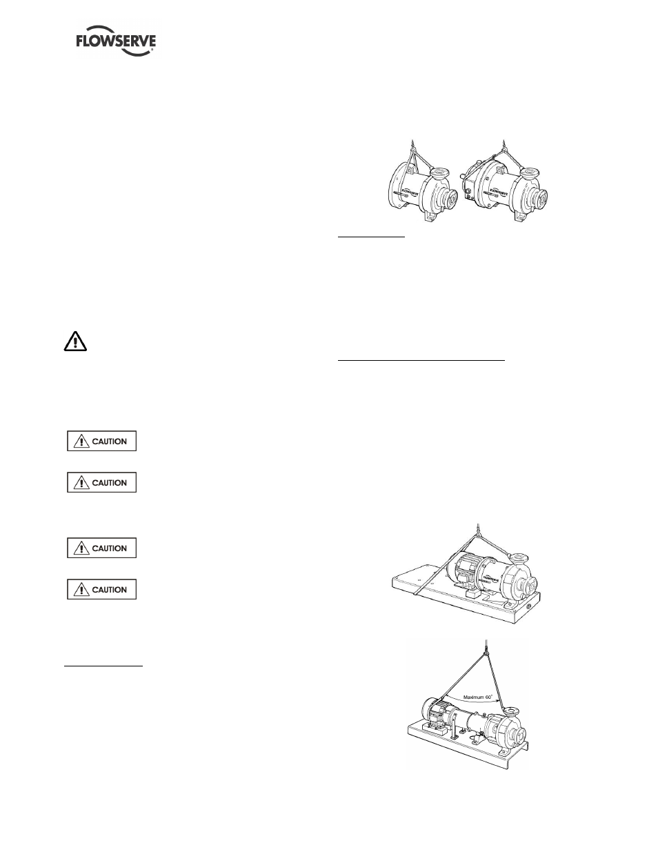
2.3.1 Bare pump
Horizontal pumps: Sling around the pump discharge
nozzle and around the outboard end of the bearing
housing or adaptor with separate slings. Choker hitches
must be used at both attachment points and pulled tight.
The sling lengths should be adjusted to balance the load
before attaching the lifting hook.
Make sure the completion of the choker hitch on the
discharge nozzle is toward the coupling end of the
pump shaft as shown in Figure 2-1.
Figure 2-1
Vertical pumps: Place one sling around the pump
discharge nozzle and one around the suction. Run the
slings up through the adaptor lifting lug to keep pump
from tipping when lifted.
2.3.2 Lifting pump, motor and baseplate
assembly
The angle between slings or ropes used for lifting
must not exceed 60°.
Horizontal pumps with motor installed: If the baseplate
has lifting holes cut in the sides at the end (Type D,
Type E bases and Type A when provided) insert lifting
S hooks at the four corners and use slings or chains to
connect to the lifting eye. Do not use slings through the
lifting holes. (Figure 2-2)
For other baseplates, sling around the pump discharge
nozzle, and around the outboard end of the motor frame
using choker hitches pulled tight. The sling should be
positioned so the weight is not carried through the
motor fan housing. (Figure 2-3)
Figure 2-2
Figure 2-3