Flowserve TB-MAG INNOMAG User Manual
Page 27
INNOMAG® TB-
MAG™ ASME and ISO SEALLESS ENGLISH 26999988 06-14
Page 27 of 44
Refer to Safety section before dismantling the
pump.
Before dismantling the pump for
overhaul, ensure genuine Flowserve Innomag®
replacement parts are available.
Refer to sectional drawings for part numbers and
identification. (See section 8, Parts lists and
drawings.)
When operating with chargeable liquids with
conductivities of <10-8 S/m, inert gases (e.g.
nitrogen) must be used to flush the pump. Before
removal of the pump it is recommended to wait one
hour to allow static peak charges to be eliminated.
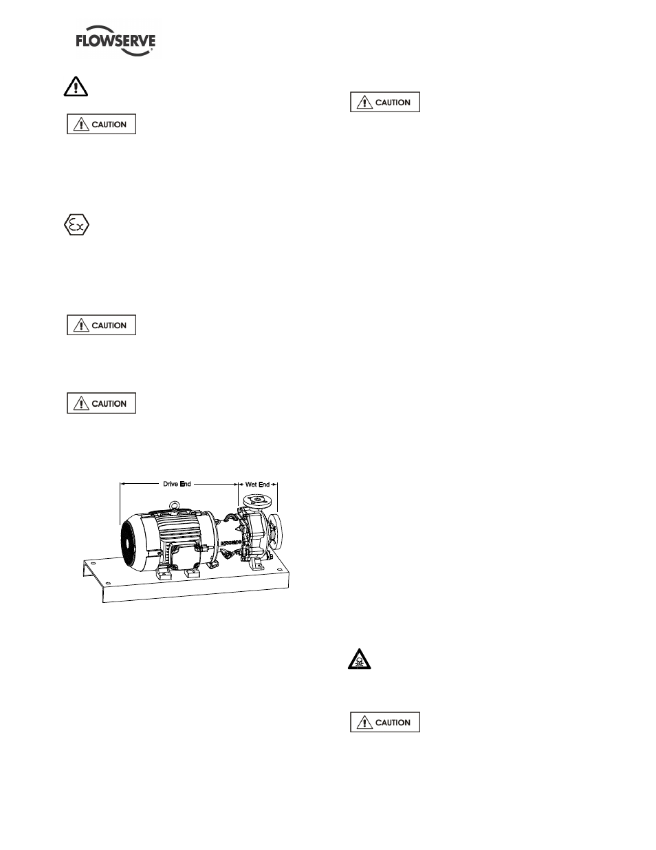
6.6.1 Drive / Wet End Separation
Flowserve Innomag® pumps
contain extremely strong magnets. The use of non-
magnetic tools and work surface is highly
recommended. The work area must be clean and
free of any ferrous particles.
Wet end and drive end separation
requires significant care. The magnetic coupling
between the impeller [2200] and outer drive [0230]
magnets is very strong. This process requires the
magnetic field between the outer drive and impeller to
be broken.
6.6.1.1 Close-Coupled and Vertical Pumps
a) Remove the bolt connecting the adapter foot
[3134] to the base and any bolts connecting the
motor to the base.
b) Remove the (4) hex caps screws [6570.1] on
the adapter [1340].
c) Separate the drive end (which includes the
adapter [1340], outer magnet assembly [0230]
and the motor) from the wet end by evenly
tightening the (2) jack bolts (see Section 6.4.1)
through the jack bolt holes in the containment ring
[3830].
Removing the close-coupled motor
requires significant care. The magnetic coupling
between the impeller and outer drive magnets is very
strong. The next step requires the magnetic field to
be broken.
d) Firmly hold the drive end and with smooth,
continuous force, pull it away from the wet end.
Pull the drive end back at least 150 mm (6 in.).
e) Turn the drive end off to the side to allow space
for disassembly of the wet end.
6.6.1.2 Long-Coupled Pumps
a) Remove the metal drain plug [6569.1] below the
sight glass [3856] on the bearing frame [3200] to
drain the oil.
b) Drain the oil into an oil pan and replace the oil
plug [6569.1].
c) Remove the coupling guard and coupling from
the motor and bearing frame shafts.
d) Remove the bolts connecting the motor to the
baseplate.
e) Move the motor aside to allow space for wet
end/bearing frame [1340] separation.
f)
Remove the bolts (2) connecting the adapter
foot [3134] to the base.
g) Remove the (4) hex caps screws [6570.1] on
the adapter [1340].
h) Separate the drive end (which includes the
adapter [1340], outer magnet assembly [0230]
and the motor) from the wet end by evenly
tightening the (2) jack bolts (see Section 6.4.1)
through the jack bolt holes in the containment ring
[3830].
i)
Firmly hold the bearing frame [3200/1340] and
with smooth, continuous force, pull it away from
the wet end.
j)
Place the bearing frame [3200/1340] aside for
disassembly of the wet end.
6.6.2 Wet End Disassembly
6.6.2.1 Wet End Disassembly – Piped Up
When handling hazardous and/or toxic fluids,
skin, eye and respiratory protection are required. If
pump is being drained, precautions must be taken to
prevent injury or environmental contamination.
Ensure suction and discharge valves
are completely closed.