Impeller repair, 11 impeller repair – Flowserve TB-MAG INNOMAG User Manual
Page 30
INNOMAG® TB-
MAG™ ASME and ISO SEALLESS ENGLISH 26999988 06-14
Page 30 of 44
half of the shaft removal tool. Adjust the bolts so
that the top of the tool is about 19mm (3/4 in.)
down the shaft [2100]
e)
Using the allen wrench, tighten the top half to
the shaft [2100]
f)
Evenly tighten the two bolts, alternating
between them when you feel resistance.
Do not use air or power tools. Do
not over tighten the bolts or you may crack the shaft
[2100].
g)
Remove the shaft [2100] from the containment
shell [3500]. Loosen and remove the shaft
removal tool.
6.10.3 Shaft Installation
a)
Align the molded key inside the containment
shell [3500] with the grooved end of the pump
shaft [2100].
b)
Place the shaft centering tool over the shaft
[2100]
c)
Place an aluminum block over the shaft [2100]
to protect it and push the shaft [2100] in using
an arbor press until the shaft [2100] is flush with
the centering tool.
d)
Remove the shaft centering tool.
e)
Place the aluminum block directly on the shaft
[2100] and press the shaft [2100] down the rest
of the way down until it is firmly seated.
6.11 Impeller Repair
6.11.1 Bushing Removal
This procedure requires the Flowserve Innomag®
bushing installation / removal kit, part # TLG-2016-
AA.
Make sure the bushing removal tool
is perfectly centered to prevent damaging the inside
of the impeller [2200]. We recommend placing a
shop towel under the impeller [2200] to prevent
damage to the SiC when it falls free.
a)
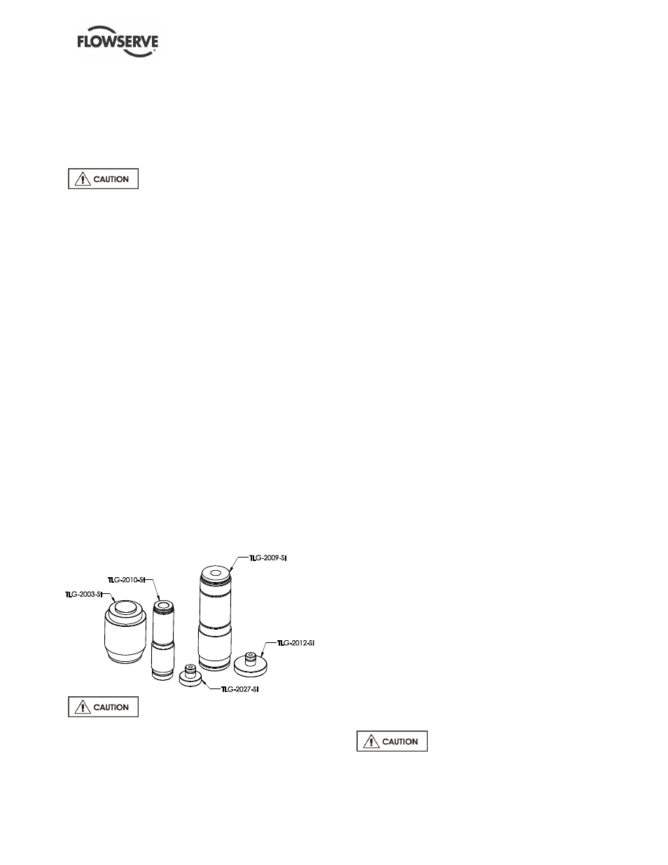
For A/V/E-Series impellers, insert TLG-2027-SI
into TLG-2010-SI and center it on the thrust
control valve [3300.2]. For B/C/W/F/G-Series use
TLG-2009-SI with TLG-2012-SI inserted.
b)
With the arbor press, carefully push the
bushings down with the removal tool until the
first bushing [3300] and spacer [3300.1]
dislodge.
c)
Lift the impeller [2200] and remove the first
bushing [3300] and spacer [3300.1] to allow
room for removing the second bushing [3300]
and thrust control valve [3300.2].
d)
Continue pressing down on the arbor press until
the second bushing [3300] and thrust control
valve [3300.2] dislodge.
e)
When the second bushing [3300] and thrust
control valve [3300.2] are free, remove the
impeller [2200].
f)
Remove the second bushing [3300] and thrust
control valve [3300.2] from the bushing removal
tool.
6.11.2 Bushing Installation
a)
This procedure requires the Flowserve
Innomag® TB-
MAG™ bushing installation /
removal kit, part # TLG-2016-AA.
b)
Place the eye of the impeller [2200] on part
TLG-2003-SI of the bushing installation toolkit.
The stepped end is designed to support all TB-
MAG™ impellers.
c)
Locate the molded key in the impeller [2200].
d)
On the underside, the thrust control valve
[3300.2] groove must line up with the molded
key.
e)
Place the thrust control valve [3300.2] over the
o-ring on the short stepped end of bushing
installation tool part TLG-2010-SI (A/V/E Series)
or TLG-2009-SI (B/C/W/F/G Series)
f)
Line up the thrust control valve [3300.2] groove
with the molded key.
g)
Carefully insert the thrust control valve [3300.2]
by hand until it stops, making sure that it is
perfectly aligned.
h)
Make sure the bushing installation tool is
perfectly centered.
i)
With an arbor press, apply slow, even pressure
to the bushing installation tool part # TLG-2010-
SI (A/V/E Series) or TLG-2009-SI (B/C/W/F/G
Series) to push the thrust control valve [3300.2]
into place. It will stop when it is firmly seated.
Do not use excessive force, as this
may damage the thrust control valve and the
impeller.