Drive end disassembly, 13 drive end disassembly – Flowserve TB-MAG INNOMAG User Manual
Page 32
INNOMAG® TB-
MAG™ ASME and ISO SEALLESS ENGLISH 26999988 06-14
Page 32 of 44
6.12.1 Piped Up Assembly
a)
Align and slide the impeller [2200] magnet
assembly onto the pump shaft [2100] located
inside the containment shell [3500].
b)
Place the assembly into the containment ring
[3830].
c)
Insert the assembled impeller [2200] and
containment shell [3500]. Carefully align the
impeller [2200] and casing [1100] wear rings.
Hold the assembly and install the containment
ring [3830]
d)
If you cannot separate the containment shell
[3500] and ring, you can insert the assembly as
one piece. Make sure the arrow on the ring
points upward.
e)
Tighten (8) hex cap screws w/lock washer.
f)
Torque the hex caps screws [6570.1] to the
specification in the Torque Table.
g)
Extend the jackscrews on the drive end. Align
the drive end and push it in until the jackscrews
meet the wet end.
h)
Retract the jackscrews until the two pump
halves are mated. Insert and tighten the (4)
adapter [1340] hex caps screws [6570.1] to the
torque given in the torque table in Section
6.11.2.
6.12.2 In-Shop Assembly
a)
With the casing [1100] face down, insert the
impeller [2200].
b)
When the impeller [2200] is in place, rotate it by
hand to make sure it spins freely.
c)
Align the shaft [2100] in the containment shell
[3500] with the bushings.
d)
Lower the containment shell [3500] into place.
e)
Place the containment ring [3830] over the
containment shell [3500] and align the bolt holes.
f)
Make sure the arrow on the containment ring
[3830] points toward the discharge flange.
g)
Insert and hand-tighten the (8) casing [1100]
bolts with lock washers.
h)
Tighten the hex cap screws [6570.1] with a
wrench and then torque them to the rating in
Figure 6-1.
Figure 6-1
Screw Size
ISO (ASME)
Torque Nm (lbf
•ft)
M10 (3/8 in.)
27 (20)
M12 (1/2 in.)
61 (45)
M16 (5/8 in.)
122 (90)
6.13 Drive End Disassembly
The outer magnet assembly [0230]
contains very strong magnets. Use caution inserting
the jack screw. Under normal circumstances a
visual inspection and wiping clean the inside of the
outer magnet is sufficient.
6.13.1 NEMA Drive End Disassembly
a)
Remove the metal pipe plug from the top of the
adapter [1340].
b)
Locate and loosen the (2) set screws on the on
the outer magnet assembly [0230] with T-handle
allen wrench - 3/16 in. (A/V/E), 1/4 in.
(B/C/W/F/G).
c)
Insert a 1/2 in. - 13 x 6+in. jack bolt into the
center of the NEMA outer magnet assembly.
d)
Tighten the jack bolt to free the outer magnet
assembly. 3/4in. socket wrench recommended
due to the magnetic forces.
e)
Carefully remove the outer magnet assembly.
f)
Remove (4) hex caps screws [6570.1] from the
adapter [1340].
g)
Remove the adapter [1340] from the motor.
6.13.2 IEC Drive End Disassembly
a)
Remove the metal pipe plug from the top of the
adapter [1340].
b)
Locate and loosen the (2) set screws on the on
the outer magnet assembly [0230] with T-handle
allen wrench - 3/16 in. (A/V/E), 1/4 in.
(B/C/W/F/G).
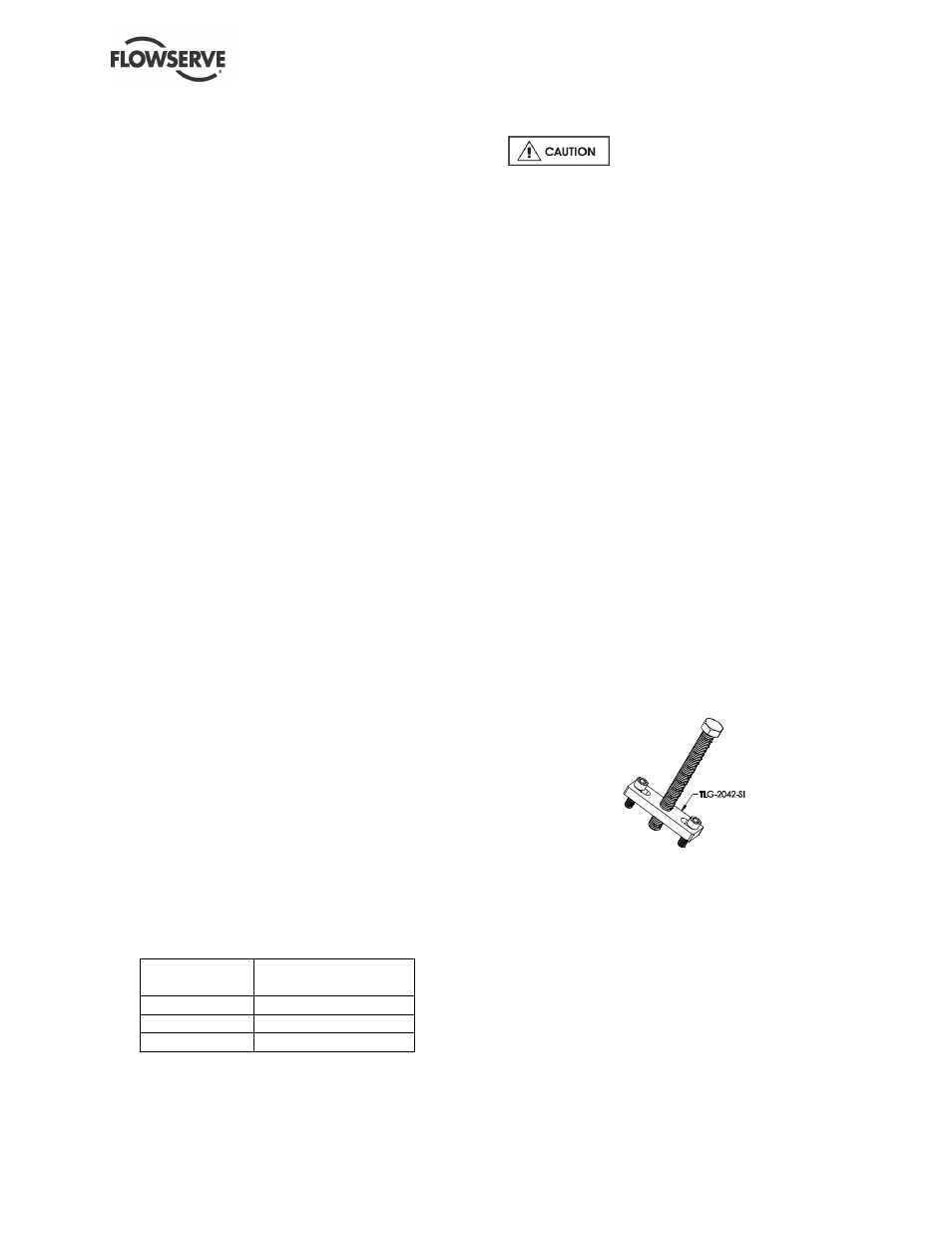
c)
Attach the jack screw plate [TLG-2042-SI] with
(2) M8 x 1.25 x 30mm screws into the treaded
holes inside the IEC outer magnet assembly
[0230].
d)
Insert a M12 x 1.75 x 100+ mm jack bolt into the
center of the jack screw plate [TLG-2042-SI] and
tighten the center jack bolt to free the outer
magnet assembly.
e)
Carefully remove the outer magnet assembly
[0230].
f)
Remove (4) hex caps screws [6570.1] from the
adapter [1340].
g)
Remove the adapter [1340] from the motor.