3 pump description, 1 configuration, 2 name nomenclature – Flowserve PHL User Manual
Page 10: 3 design of major parts, 4 performance and operating limits
PHL USER INSTRUCTIONS ENGLISH 00079593
– 10/10
Page 10 of 31
and or gases that may be used in the "seal system" or
other utilities.
Make sure that hazardous substances are
disposed of safely and that the correct personal
protective equipment is used. The safety
specifications shall be in accordance with the current
regulations at all times.
3 PUMP DESCRIPTION
3.1 Configuration
The PHL type pump is a heavy duty, single stage,
horizontal centrifugal pump, designed for the
Petrochemical Industry, chemical plants, general
service and circulating applications.
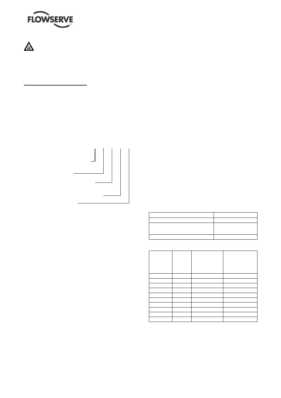
3.2 Name nomenclature
The pump size will be engraved on the nameplate
typically as below:
PHL 30.20.15.30F
Configuration
– see 3.1 above.
Max. impeller size (cm)
Nominal suction branch size (cm)
Nominal discharge branch size (cm)
Specific hydraulic design
The typical nomenclature above is the general guide
to the PHL configuration description. Identify the actual
pump size and serial number from the pump
nameplate. Check that this agrees with the applicable
certification provided.
3.3 Design of major parts
3.3.1 Pump casing
The pump has its main casing gasket axial to the shaft
allowing maintenance to the rotating element by
removing the back pull out unit. Suction and discharge
branches are at the casing and therefore its piping
remain undisturbed at maintenance.
3.3.2 Impeller
The impeller is fully shrouded and is fitted with
impeller wear rings.
3.3.3 Diffuser
The diffuser is tuned to the impeller and the multi
channel diffuser is concentric aligned around the
impeller
3.3.4 Pump Shaft
The pump is of the dry shaft design and has a keyed
drive end.
3.3.5 Stuffing box
The stuffing box has a spigot (rabbet) fit between
the pump casing and seal plate for optimum
concentricity. The design enables a number of
sealing options to be fitted.
3.3.6 Shaft seal
The mechanical seal(s) attached to the pump shaft
seals the pumped liquid from the environment.
Gland packing may be fitted as an option, for non-
hazardous service only.
3.3.7 Driver
The driver can be an electric motor or diesel motor
or turbine.
3.3.8 Accessories
Accessories may be fitted when specified by the
customer.
3.4 Performance and operating limits
This product has been selected to meet the
specifications of your purchase order. See section
1.5.
The following data are included as additional
information to help with your installation. It is typical,
and factors such as temperature, materials, and seal
type may influence these data. If required, a definitive
statement for your particular application can be
obtained from Flowserve.
3.4.1 Operating limits
Pumped liquid temperature limits*
up to +450 ºC (842 ºF)
Maximum ambient temperature*
up to +40 ºC (104 ºF)
Maximum soft solids in
suspension*
up to 1 % by volume
(refer for size limits)
Maximum pump speed
up to 3600
3.4.2 Pump and impeller data
Pump size
Impeller
maximum
size
mm (in.)
Nominal wear
ring diameter
Small / large
mm (in.)
Min.
diametral
wear ring
clearance
mm (in.)
PHL 25.08.05
240 (9.45
90/130 (3.54/5.12) 0.35/0.43 (0.014/0.017)
PHL 25.10.08 235 (9.25)
130/-- (5.12/--)
0.43/-- (0.017/--)
PHL 25.15.10
242 (9.53
165/200 (6.50/7.87) 0.45/0.50 (0.018/0.020)
PHL 30.20.15 290 (11.4) 220/265 (8.66/10.43) 0.50/0.55 (0.020/0.022)
PHL 35.08.05 370 (14.57) 100/130 (3.93/5.12 0.35/0.43 (0.014/0.017)
PHL 35.10.08 370 (14.57) 130/140 (5.12/5.51) 0.43/0.43 (0.017/0.017)
PHL 35.15.10 354 (13.93) 180/200 (7.09/7.87) 0.48/0.50 (0.019/0.020)
PHL 40.10.08 420 (16.54) 140 / 140 (5.51/5.51) 0.43/0.43 (0.017/0.017)
PHL 40.15.10 420 (16.54) 170/195 (8.66/10.83) 0.48/0.50 (0.019/0.020)
PHL 40.20.15 420 (16.54) 220/290 (8.66/11.41) 0.50/0.60 (0.020/0.025)