5 fastener torques (typical), 6 setting impeller clearance, 7 disassembly – Flowserve PHL User Manual
Page 22
PHL USER INSTRUCTIONS ENGLISH 00079593
– 10/10
Page 22 of 31
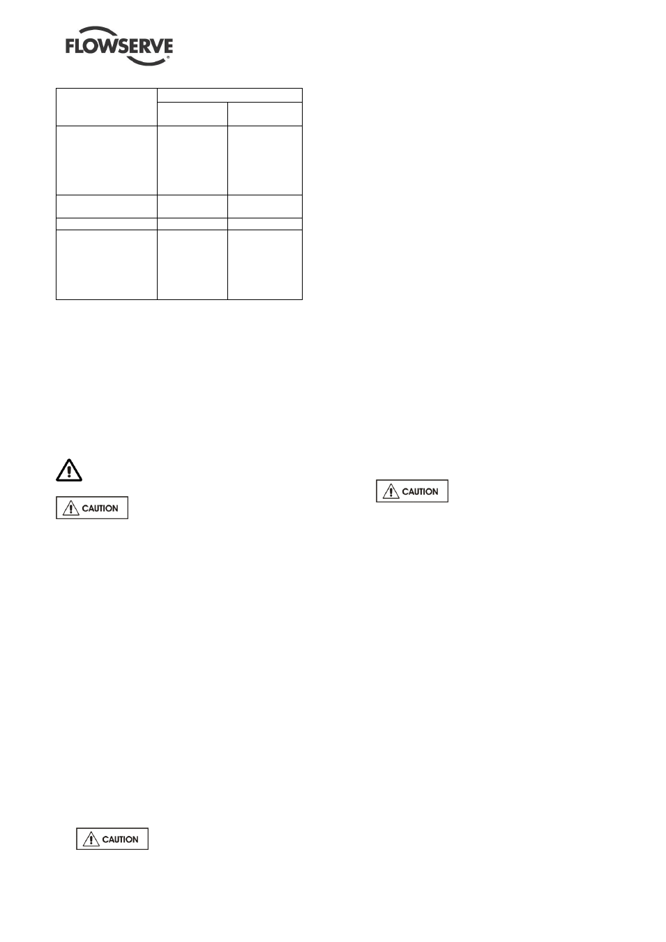
6.5 Fastener torques (typical)
Application
Torque Nm (lbft)
Lubricated
Non-
lubricated
Casing studs
M 12
M 16
M 20
M 24
M 30
55 (41)
110 (81)
170 (126)
247 (182)
519 (383)
65 (48)
165 (122)
285 (211)
375 (277)
540 (399)
Seal studs, all cases
(back mounted seal)
125
145
Packed gland studs
Finger tight
Finger tight
Impeller screw
M8
M12
M16
M20
M24
6 (4.5)
23 (17)
57 (42)
114 (84)
180 (133)
7 (5.2)
25 (18)
60 (44)
120 (89)
190 (140)
6.6 Setting impeller clearance
As wear takes place between the impeller and casing
ring the overall efficiency of the pump set will
decrease. To maintain optimum efficiency it is
recommended that rings are replaced and the impeller
renovated when the diametral clearance detailed in
section 3.4.2 has doubled to 0.7 to 1.1 mm (0.028 to
0.043 in.), depending on pump size and wearing ring
diameter.
6.7 Disassembly
Refer to section 1.6, Safety, before dismantling
the pump.
Before dismantling the pump for
overhaul, ensure genuine Flowserve replacement
parts are available.
Refer to sectional drawings for part numbers and
identification.
6.7.1
Removing the spacer
If applicable, remove the spacer of the coupling
between the pump unit and the electric motor
according to the suppliers documentation.
6.7.2 Removing the 'back pull out' unit
The 'back pull out' unit is removed by following the
procedure given below:
remove the nuts [6581.1] from the casing cover.
attach the lifting devices to the appropriate lifting
points, see Figure 1. Observe the lifting
instructions described in section 2.3.
lift the casing cover up. Work carefully as there is
not much clearance between the diffuser and the
pump casing.
remove the packing ring [4590.2] from the pump
casing and dispose of this in the proper way.
This type of packing may only be
used once.
6.7.3 Removing the diffuser
This procedure describes removal of the diffuser
from the casing cover.
Bend open the lock washers [6541] and
remove the hexagon head bolts [6577.1] from
the diffuser.
Remove the diffuser.
6.7.4
Removing the impeller
This procedure describes removal of the impeller
from the pump shaft.
fix the mechanical seal to the shaft sleeve by
using the setting plates on top of the
mechanical cover
undo the impeller screw [2913] with left-hand
thread. The impeller screw is locked in the bore
hole in the impeller by twisting the impeller
screw.
remove the impeller screw and the packing ring
[4590.1] between impeller and impeller screw.
This type of packing may only be used
once. Dispose of the packing ring in the proper
way.
push the impeller from the pump shaft and
remove the released key [6700.1].
remove packing ring [4590.3] between the
impeller and the stub sleeve of the mechanical
seal.
This type of packing may only
be used once. Dispose of the packing ring in
the proper way.
6.7.5
Removing the bearing bracket
The mechanical seal is mounted on the back of the
casing cover which means that the bearing bracket
has to be detached from the casing cover before
disassembling the mechanical seal.
Place the bottom of the casing cover on a flat
surface.
Remove the set screws from the shaft sleeve to
make the mechanical seal cartridge loose.
Remove the bolts [6577.5].
Lift the pump bracket up vertically. Work
carefully as long as the pump shaft is still
inserted in the shaft sleeve.