Not supplied, 4 adjusting the foundation frame – Flowserve PHL User Manual
Page 12
PHL USER INSTRUCTIONS ENGLISH 00079593
– 10/10
Page 12 of 31
Fill the space between the filler blocks and the
foundation frame with filler plates.
Check that the bolts fit easily into the bolt holes of
the flanges.
Fix the foundation bolts by filling the recesses with
non-shrinkable mortar.
Let the mortar set in accordance with the
specifications.
4.4
Adjusting the foundation frame
To make sure that the unit is leveled, use a calibrated
machine levelwith an accuracy of 0.02 mm/m
1
.
Measure along the shaft of the electric motor in both
directions, or, if this is not possible, along the seal
plate. If the mechanical seal is fitted with a guard, this
should be removed.
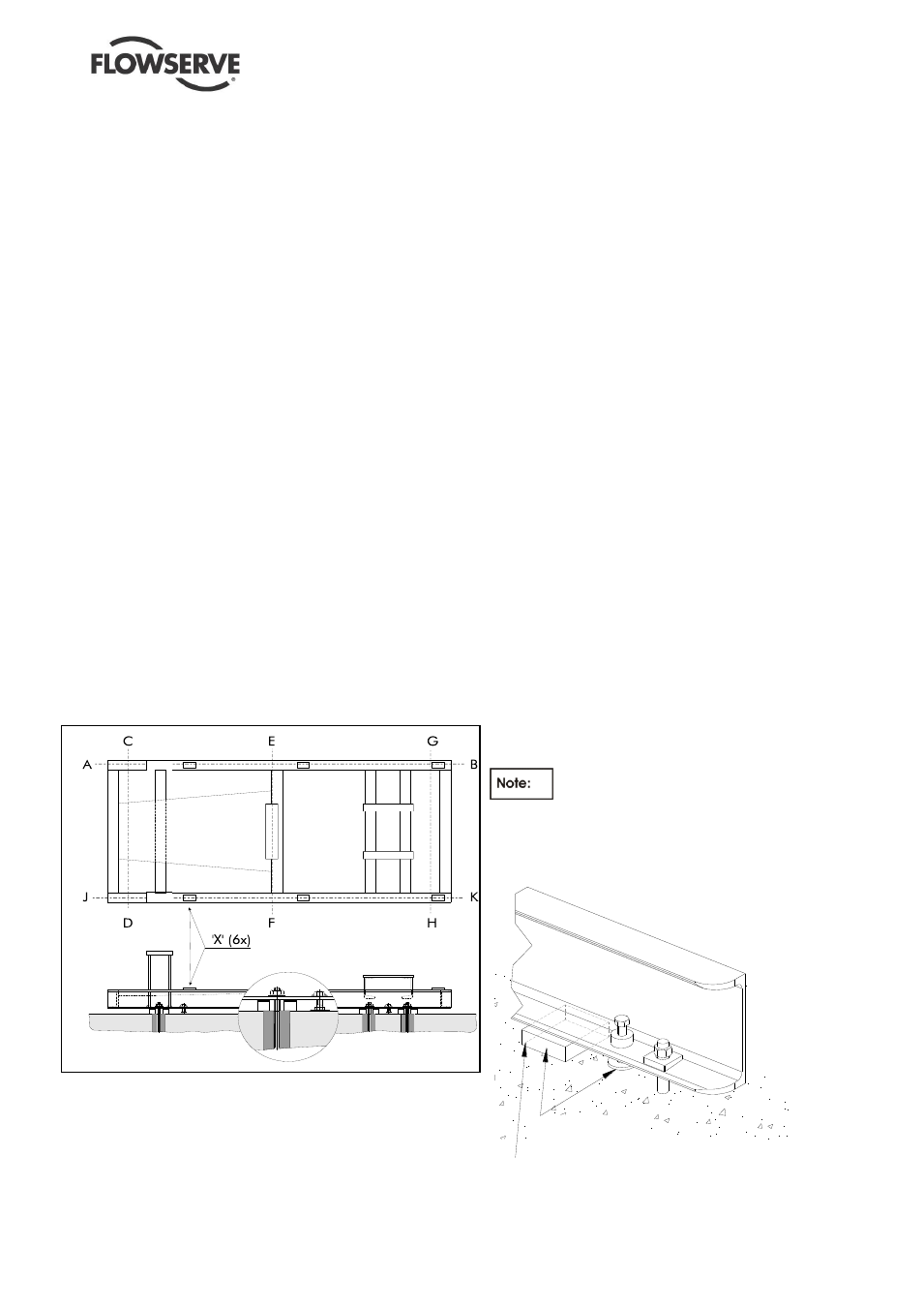
Level the foundation frame in the direction A-B
with an accuracy of 0.05 mm/m
1
using the
adjusting bolts, see Figure 3. Fill the space
between the filler blocks and the foundation frame
with thin filler plates.
Tighten the foundation nuts, along the A-B axis, by
applying a moment equal to ¼ the maximum
permissible moment (M
max
) of the foundation bolt.
Level the foundation frame in the directions C-D,
E-F and G-H with an accuracy of 0.05 mm/m
1
using the adjusting bolts. Fill the space between
the filler blocks and the foundation frame with thin
filler plates.
Tighten the other foundation nuts by applying a
moment equal to ¼ the maximum permissible
moment (M
max
) of the foundation bolt.
Check that the nuts of the foundation bolts are still
tight.
Place the electric motor on the pump center line,
using shims between the supporting faces of the
foundation frame and the motor base.The
maximum allowable deviation in axial or radial
direction is 0.05 mm and depends on the type of
coupling.
Retract all foundation bolts and check that the
foundation frame is level in all directions with
an accuracy of 0.05 mm/m
1
.
Check the position and level along the center
line of the suction and discharge nozzles.
Adjust, if necessary, by following the
procedures given above.
Fill in the outer edges of the foundation frame,
including filler plates, completely, using non-
shrinkable mortar (e.g. Pagel V1 or equivalent)
and let this set in accordance with the
specifications.
Grout the foundation frame, via the fill opening
(see Figure 3), completely, using non-
shrinkable concrete and let this set in
accordance with the specifications.
Check that the nuts of the foundation bolts are
still tight and tighten, if necessary, by applying
the correct moment (¼ M
max
).
If the guard of the mechanical seal was
removed for levelling, replace it in the correct
position.
If necessary, draw up a report on the whole
adjustment procedure.
4.4.1 Baseplate not Intended for Grouting but
Installed on Concrete Foundations
According to the figure 4.3.1 and 4.4.1 the
baseplate will not be grouted but only a sealing
shall be provided. During the preparation, as
indicated on the General Arrangement drawing a
certain number of openings into the sealing must
be guaranteed. After the sealing the blocks used to
realise the openings must be removed. Blocks has
to be wider than the baseplate longitudinal beam in
order to guarantee the opening for the drainage.
The filler grout must be of a non-
shrinkable kind and fill up the space between the
beams and the concrete poor. Make sure that filler
grout is dry before removing the blocks.
Not supplied
BLOCK TO BE REMOVED
AFTER THE SEALING
Figure 4.3.1
Figure 3: Adjusting foundation frame
BLOCK TO BE REMOVED AFTER
APPLYING THE FILLER GROUT