5 initial alignment – Flowserve PHL User Manual
Page 13
PHL USER INSTRUCTIONS ENGLISH 00079593
– 10/10
Page 13 of 31
TOP OF FOUNDATION
PRIMARY
CONCRETE
SEALING
Figure 4.4.1
4.5 Initial alignment
4.5.1 Thermal expansion
The PHL pump and motor are designed such that they
will cope with the thermal expansion for pump
application and cope with the pumping temperature as
specified on the pump data sheet. There is no need to
check the alignment at normal service conditions.
4.5.2 Alignment methods
Ensure pump and driver are isolated
electrically and the half couplings are disconnected.
The alignment MUST be checked.
Although the pump will have been aligned at the
factory it is most likely that this alignment will have
been disturbed during transportation or handling. If
necessary, align the motor to the pump, not the pump
to the motor.
4.5.2.1 Shaft/Coupling alignment
Shaft alignment must be correct for
successful operation. Rapid wear, noise, vibration
and actual damage to the equipment may be
caused by shaft misalignment. The shafts must be
aligned within the limits given within this section.
Adjustment to correct the alignment in one
direction may alter the alignment in another direction.
Always check in all directions after making any
adjustment.
Coupled equipment must be aligned to minimise
unnecessary stresses in shafts, bearings and
coupling. Flexible couplings will not compensate for
appreciable misalignment. Foundation settling,
thermal expansion or nozzle loads resulting in
baseplate/foundation deflection and vibration during
operation may require the full coupling misalignment
capability.
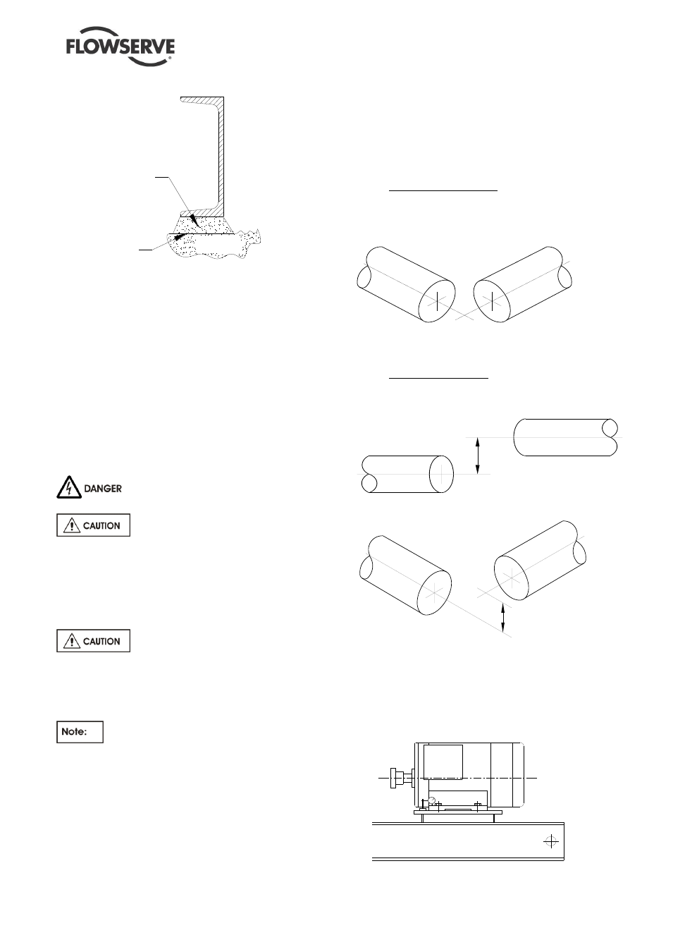
4.5.2.1.1 Types of misalignment
There are two types of shaft misalignment: angular
and offset. Therefore, two sets of measurements
and corrections are required. Both types of
misalignment can occur in horizontal and vertical
planes and are present in most applications.
A)
Angular misalignment
In angular misalignment, the centre line of the
shafts intersect, but are not on the same axis.
Figure 4.5
B)
Offset misalignment
In offset misalignment, the shaft centre lines are
parallel but do not intersect.
OFFSET MISALIGNMENT
Figure 4.6.1
– offset misalignment
COMBINATION OFFSET
AND
ANGULAR MISALIGNMENT
Figure 4.6.2
– combination of offset and angular misalignment
4.5.2.2 Alignment using the Reverse Alignment
Method
The following practices are recommended when
using the reverse method of alignment. These
should be carried out prior to main alignment.
Figure 4.7
FILLER GROUT