Flowserve PHL User Manual
Page 23
PHL USER INSTRUCTIONS ENGLISH 00079593
– 10/10
Page 23 of 31
6.7.6 Removing the mechanical seal
This procedure describes removal of the mechanical
seal from the casing cover.
Remove the nuts [6581.2] from the mechanical
seal on top of the cover.
Remove the mechanical seal.
Do not dismantle the mechanical seal any further.
For further information on the mechanical seal, please
refer to the instructions for use provided by the
mechanical seal supplier.
6.7.7 Removing the case wearing rings
This is the procedure to be followed when removing
the case wearing ring (2300.1) from the diffuser and, if
applicable, the wearing ring in the casing cover
(2300.2).
The case wearing ring (2300.2) has been pressed or
shrunk into the centring rim during assembly which
means that it will be necessary to drill or cut into the
case wearing ring in order to weaken the upright edge.
Remove the set screws [6570.1/3]. These set
screws lock the case wearing ring on the diffuser
[1410].
Measure width & height of the case wearing ring.
Take a drill with a slightly smaller diameter than
the width of the case wearing ring.
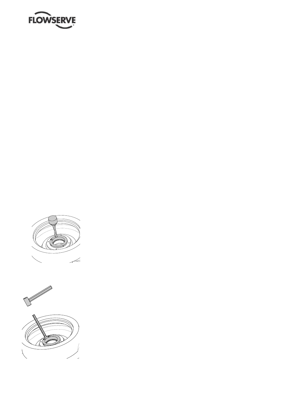
Drill two holes along
the centre line of the
upright edge of the
case wearing ring,
see Figure. Drill both
holes not deeper than
the measured height
of the case wearing
ring.
Chip off the remaining
edges of the drilled
holes using a
hammer and chisel,
see Figure. Make
sure that the centring
rim is not damaged.
Remove the halves of
the case wearing ring
and the metal chips
from the diffuser or
casing cover.
6.7.8 Removing the impeller wearing rings
The impeller wearing rings [2300.1/2] have been
shrunk or pressed onto the impeller during
assembly. Therefore a suitable extraction tool must
be used for disassembly.
Remove set screws [6570.2]. These set screws
lock the impeller wearing ring on the impeller.
Remove the impeller wearing ring from the
impeller using the extraction tool.
Drill 3 holes at 120
intervals in the partition
between impeller wearing ring and impeller.
Drill the holes to a depth such that the set
screws [6570.2] do not protrude above the
surface of the impeller wearing ring and
impeller.
6.7.9 Removing the throat bush
This procedure describes removal of the throat
bush from the casing cover.
Remove set screws [6570.3] from the bottom of
the casing cover. These set screws lock the
throat bush [4132] in the casing cover.
Remove the throat bush from the casing cover.
If this cannot be done by hand, remove it from
the casing cover by tapping with a suitable
copper rod and a hammer.
6.7.10 Removing the throwers
This procedure describes removing the throwers
from the pump shaft.
Untighten the set screws from the throwers
(2540.1/2)
Remove the throwers from the pump shaft.
6.7.11 Removing the bearing covers
This procedure describes removing the bearing
cover from the bearing housing.
Remove the bolts (6577.2 and 6577.3) from the
bearing housing (3200).
Remove the bearing covers (3260.1 and
3260.2).
6.7.12 Removing the bearings from the bearing
housing
This procedure describes removing the radial roller
bearing and the axial ball bearing from the bearing
housing.
Remove the pump shaft from the bearing
housing by hitting carefully, with a plastic or
lead hammer, the impeller side of the pump
shaft. The inner ring of the radial roller bearing
(3012) and the complete axial ball bearing
(3013) will shove out of the bearing housing.
Remove the outer ring of the radial roller
bearing (3012) from the bearing housing.
Figure : Drilling of the case wearing
ring
Figure : Removing the case
wearing ring