4 general description – Flowserve PLEUGER User Manual
Page 11
PLEUGER STANDARD USER INSTRUCTIONS ENGLISH 71569293 01-13
Page 11 of 40
flowserve.com
3.3 General data
3.3.1 Normal operating conditions
Temperature: see data sheet
Sand content: max. 25 mg/l (0.03 oz/fl.oz)
Water velocity along motor surface: see data
sheet
No impurities that could lead to deposits and
blockages within the pump or to deposits on the
motor surface
No water hammer
Maximum 3 minutes operation against closed
slide valve
Refer to section 7.1.2., First
switching on.
Operation within prescribed voltage tolerances
Permissible operational range: 50 to 120 % of the
best efficiency point (BEP)
Correctly selected and adjusted motor protection
Observation of the maximum permissible starting
frequency
If other working conditions are
required please contact Flowserve for advice.
At higher ambient temperatures
and/or lower flow velocities on the external motor
surfaces, or if there is risk of clogging, special
measures for heat dissipation are required. This
must be checked with the manufacturer by indicating
the ambient conditions. In this case the suitability of
the unit for its planned application must be confirmed
by the manufacturer.
3.4 General description
Submersible-motor pumps are subjected to a thorough
inspection before leaving the factory and are supplied
with operating instructions for fitting, starting and care
that conform to general safety regulations.
Standard submersible-motor pumps are used to
transport cold clean water under normal operating
conditions.
The Pleuger submersible-motor pump has been
developed for installation in wells and as a result has a
distinctive slim design. The Pleuger submersible-motor
pump, because of its various features, can also be used
for other applications with different design modifications.
The submersible motor pump consists of a submersible
motor, a submersible pump and usually a check valve.
The complete pump unit is freely suspended on the
rising main which is supported at the wellhead.
Other uses or applications must be agreed by the
manufacturer.
Power cables and, if applicable, signal cables are
fixed to the riser pipes by means of cable clips.
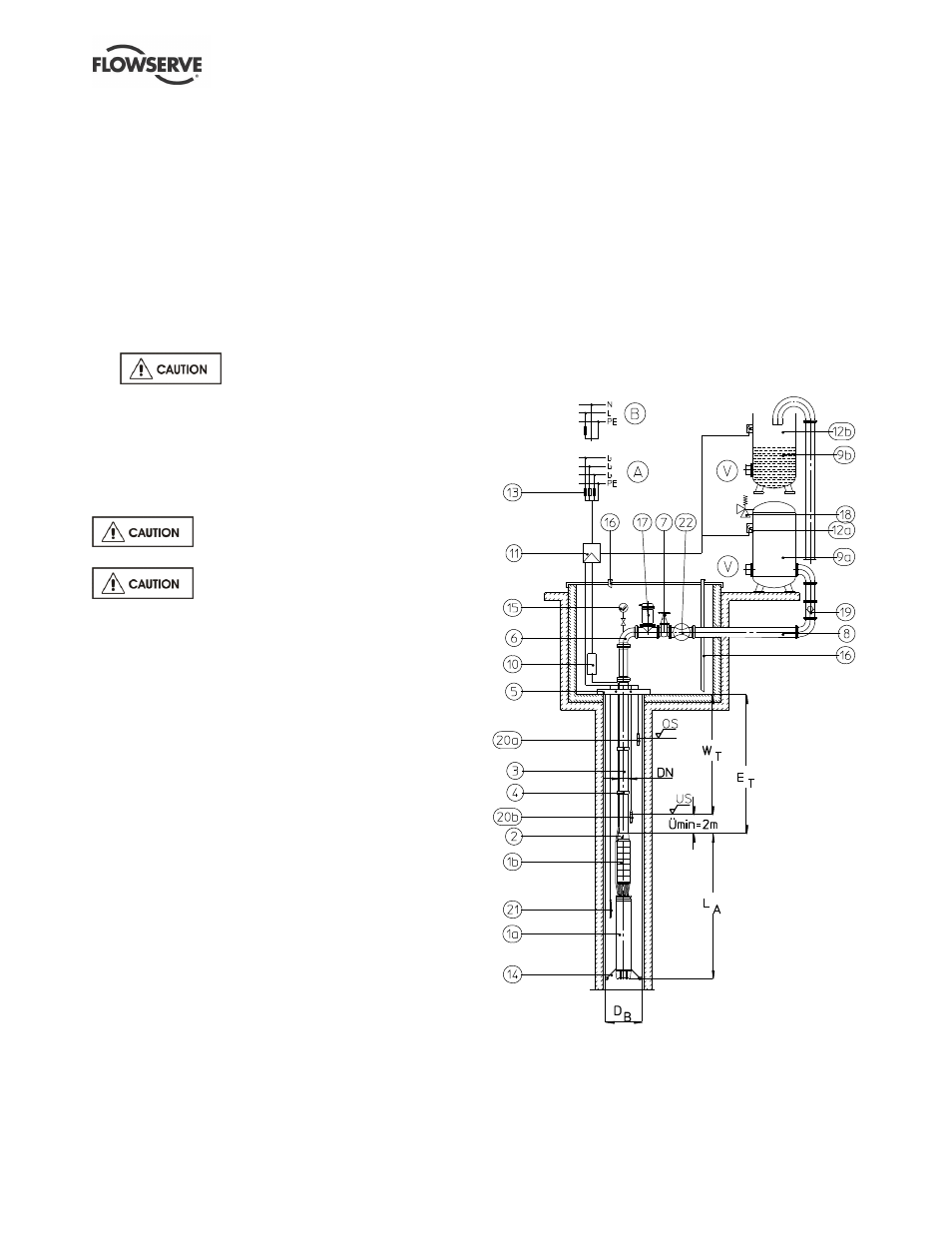
The ideal construction of a water supply system is
shown in figure 3-1. Since this shows a basic
arrangement, the actual layout must be adapted to
local and technical conditions.
The additional listed components are
recommendations for operational safety and the
protection of the pump unit.
Figure 3-1: Water supply system