Flowserve PLEUGER User Manual
Page 27
PLEUGER STANDARD USER INSTRUCTIONS ENGLISH 71569293 01-13
Page 27 of 40
flowserve.com
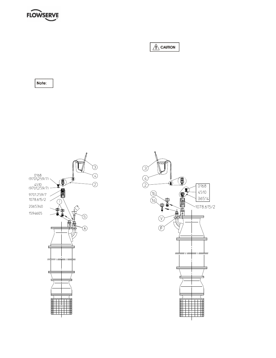
6.6.6 MP6 Polder motors
(See figure 6-6.)
a) Position the unit with the motor vertical and
prevent the unit from falling over.
b) Screw off the cap nuts including plug [1] from the
filling and return pipes [A].
c) To fill or top up the motor, insert a funnel [5] into
one of the two pipes and pour in the liquid until it
escape with no bubbles from the other pipe.
Filling and vent pipes of this type of
polder motors do not generally have identifying
markings, therefore either pipe can be selected.
d) To enable the filling of the motor with a pump [3]
a filling valve [9701.259/7] together with an
adapter piece [1078.615/2] must be fitted onto
one of the pipes. For the supplementary
installation the following parts (not supplied as
standard) are required:
1 x adapter piece TLN 1078.615/2
1 x filling valve TLN 9701.259/7
1 x filling nipple [2] TLN 9452.558/2
1 x filling pump [3] with filling hose
Figure 6-6
Alternatively, large motors can be filled with a
filling pump via a pressurised water connection.
The filling pressure at the inlet of
the screw connection must not exceed 0.5 bar
(7.25 psi) maximum when connected to a water
supply such as a household tap.
e) After filling, unscrew the filling valve and the
adapter piece and screw the cap nuts including
plugs [1] back onto the filling and return pipe.
6.6.7 Filling and topping up MP 8/MIP 10 motors
for polder pumps using a filling pump (with filling
and venting pipe on top)
(See figure 6-7.)
a) Position the unit with the motor vertical and
prevent the unit falling over.
b) Screw off the cap nuts with plug [1a] (thread size
M12x1.5) from the venting p
ipe “V” and [1b]
(thread size M16x
1.5) from the filling pipe “F”.
c) Screw in a filling valve [9701.259/7] together with
an adapter piece [1078.615/2] onto the thread for
the cap nut [1b].
Figure 6-7