Flowserve PLEUGER User Manual
Page 28
PLEUGER STANDARD USER INSTRUCTIONS ENGLISH 71569293 01-13
Page 28 of 40
flowserve.com
d) Unscrew the plug screw [0168] from the filling
valve [9701.259/7] and fit a filling nipple [2] into
the threaded hole.
e) Using the filling pump [3] fill the motor until the
liquid escapes from the return pipe “V” with no
bubbles.
f) After filling, unscrew the adapter piece and the
filling valve and screw the cap nut and plug
screws back onto the filling and return pipes. For
the supplementary installation the following parts
(not supplied as standard) are required:
1 x adapter piece TLN 1078.615/2
1 x filling valve TLN 9701.259/7
1 x filling nipple [2] TLN 9452.558/2
1 x filling pump [3] with filling hose
Large motors can be filled via a pressurised
water connection. For this a hose can be pulled
onto the filling nipple [2].
The filling pressure at the inlet of
the screw connection must not exceed 0.5 bar
(7.25 psi) maximum when connected to a water
supply such as a household tap.
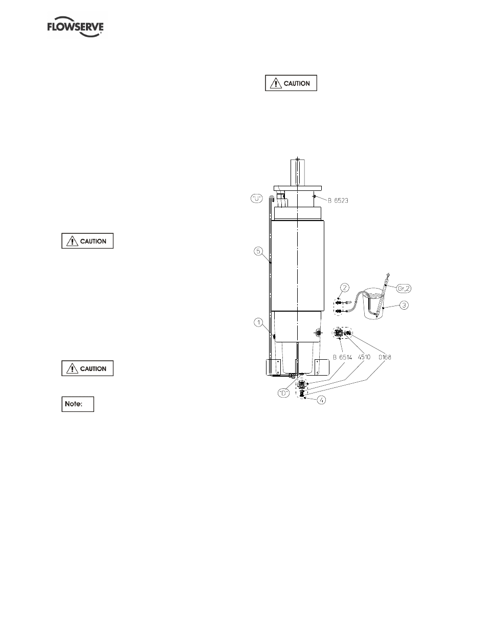
6.6.8 Filling motors with external pressure
equalization (outside compensation pipe)
(See figure 6-8.)
a) Position the unit with the motor vertical and
prevent the unit from falling over.
b) Remove the vent screw [1].
c) Remove the inner screw plug [0168] of the filling
valve [B 6514].
Handle seal ring [4510] with care.
d) Screw the filling nipple [2] into the threaded hole
from which the screw plug [0168] was removed.
The hose connections of the filling
nipples are different sizes. The correct one must
be fitted according to the thread size (M10 or
M16) and the pump hose size.
e) Fit the hose end of the filling pump supplied over
the nipple [2] and place the pump in a container
[3] filled with liquid.
f) Fill the motor until the liquid escaping from the
opening for the vent screw [1] contains no
bubbles. Refit the vent screw [1].
g) Continue filling the motor via the filling valve
[B6514] until the liquid escaping from the vent
valve [B 6523] contains no bubbles.
h) For filling the motor, it is recommended to
completely screw out the vent valve.
i)
Refit the screw plug [0168] into the filling valve
[B6514] together with its seal ring [4510].
j)
Remove the inner screw plug [0168] of the filling
valve [4].
Handle seal ring [4510] with care.
k) Screw the supplied filling nipple [2] into the
threaded hole from which the screw plug [0168]
was removed, and fill the expansion pipe [5] until
the liquid escapes from the top end "U".
l)
Screw the filling nipple out of the filling valve [4]
and refit the screw plug [0168] into the filling
valve together with the seal ring [4510].
6.6.9 Motors for horizontal installation
(See figure 6-9A, as delivered state)
(See figure 6-9B, operating state)
a) Fill or top up the motor before installation, as
described in section 6.6.1 or 6.6.2.
b) Replace the vent valve [B6523] by a screw plug
[6780] (marked
“A”.)
c) Put the motor or complete pump unit into its
horizontal position for normal use so that the
carriers located on the stator housing (marked
“B”) are at the highest point of the stator housing.
d) Screw the two plugs [6780] out of the carriers and fit
vent valves [B6523] in their place (marked “B”).
e) Exchange the screw plugs [6780] for vent valves
[B6523]. This must be carried out immediately
before installation on site.
Figure 6-8