5 motor connection diagrams – Flowserve PLEUGER User Manual
Page 18
PLEUGER STANDARD USER INSTRUCTIONS ENGLISH 71569293 01-13
Page 18 of 40
flowserve.com
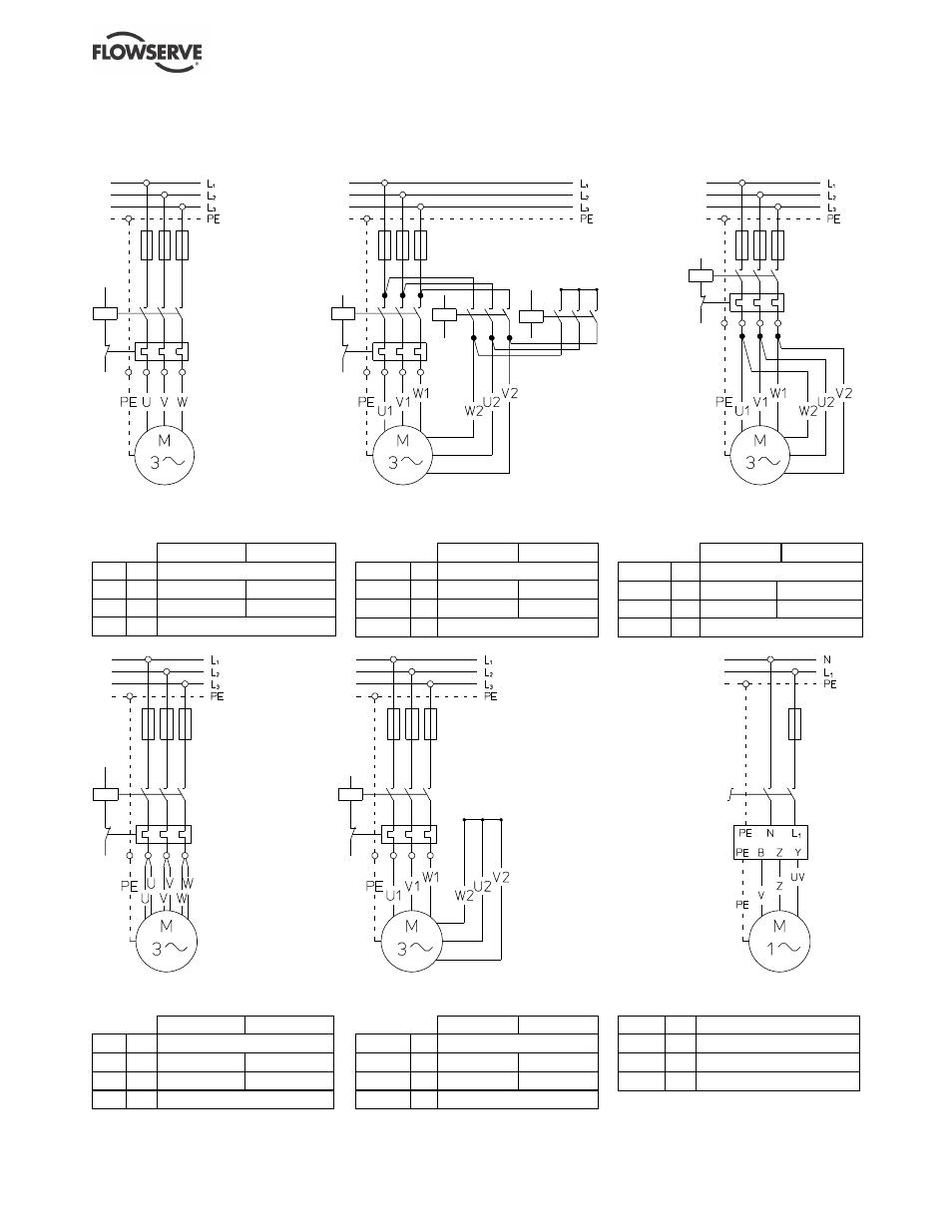
5.5 Motor connection diagrams
5.5.1 Clockwise rotation
Figure 5-1: Direct-on-line-starting
- one power supply cable
Old
New
U
=
black
V
=
light blue
brown
W
=
brown
grey
PE
=
green/yellow
Figure 5-3: Star-delta-stating
Old
New
U
1
/U
2
=
black
V
1
/V
2
=
light blue
brown
W
1
/W
2
=
brown
grey
PE
=
green/yellow
Figure 5-5: Direct-on-line-starting -
delta-connection in control panel
Old
New
U
1
/U
2
=
black
V
1
/V
2
=
light blue
brown
W
1
/W
2
=
brown
grey
PE
=
green/yellow
Figure 5-2: Direct-on-line-starting
- two power supply cables
Old
New
U
=
black
V
=
light blue
brown
W
=
brown
grey
PE
=
green/yellow
Figure 5-4: Direct-on-line-starting
- star-connection in control panel
Old
New
U
1
/U
2
=
black
V
1
/V
2
=
light blue
brown
W
1
/W
2
=
brown
grey
PE
=
green/yellow
Figure 5-6: Single-phase motor
V
=
light blue
UV
=
brown
Z
=
black
PE
=
green/yellow