Ab c, De f – Flowserve MNV User Manual
Page 13
Advertising
MNV & MNZ USER INSTRUCTIONS ENGLISH 71569188 11/04
Page 13 of 47
®
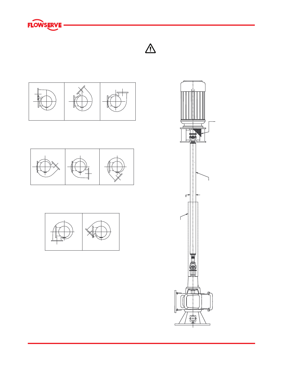
3.1 Nozzle configurations
The MNV and MNZ pumps are configured with
various nozzle positions, designated A-H as shown
(Example: for counter clock-wise rotation).
A
B
C
D
E
F
G
H
3.1.1 Long shafting with U-joints.
(Example shown is MNZ pump assembly).
Shaft guards are supplied if ordered. It is the
responsibility of the operators of drive shaft and
universal joints to provide and install guards or safety
devices, which may be required by recognized safety
standards.
GUARD
U SHAFTING
TUBING
SHAFT
GUARD
Advertising