4 performance and operating limits – Flowserve MNV User Manual
Page 15
MNV & MNZ USER INSTRUCTIONS ENGLISH 71569188 11/04
Page 15 of 47
®
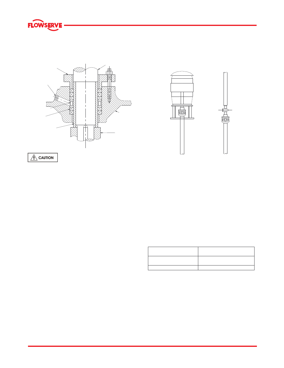
The number of packing rings list is provided in
section 6.1.8.1. Place two rings of packing below the
seal cage and the remaining rings above the seal
cage.
PUMP SHAFT
STUFFING BOX
HEAD
IMPELLER
PACKING GLAND
SEAL WATER
CONNECTION
SEAL CAGE
SHAFT SLEEVE
PACKING
The stuffing box is not packed when
the pump is shipped
.
A water supply of approximately 0.113 to 0.227 m
3
/h
(0.5 to 1.0 gpm) is to be introduced to the seal water
connection to provide for packing lubrication and
sealing. A steady "trickle" of water from the stuffing
box will indicate proper adjustment. The sealing
water supply pressure should be 0.35 to 0.69 bar (5
to 10 psi) above the pump discharge pressure.
When grease sealing is used, a similar grease
pressure should be maintained. A slight leakage of
liquid from the stuffing box is to be expected and the
gland
MUST NOT
be tightened to the point of
stopping the leakage.
3.3.7 Shaft seal
The mechanical seal(s) attached to the pump shaft
seals the pumped liquid from the environment.
Gland packing may be fitted as an option. See
section 6.1.9 for mechanical seal maintenance
information.
3.3.8 Driver
The driver is normally an electric motor. Different
drive configurations may be fitted such as internal
combustion engines, turbines, hydraulic motors etc.,
driving via couplings, belts, gearboxes, drive shafts.
All metal flexible couplings are normally used for
connecting pump and drive shafts. For operating
instructions, refer to the coupling manufacturer's User
Instructions.
3.3.9 Intermediate shafting
Steel flexible shafting with universal joint couplings is
usually used with MNV/MNZ pump installations. For
operating instructions, refer to the U shaft
manufacturer's User Instructions. See below for
illustrations of driver and intermediate U-joint shafting.
3.3.10 Accessories
Accessories may be fitted when specified by the
customer
3.4 Performance and operating limits
This product has been selected to meet the
specifications of your purchase order. See section 1.5.
The following data is included as additional information to
help with your installation. It is typical, and factors such
as temperature, materials, and seal type may influence
this data. If required, a definitive statement for your
particular application can be obtained from Flowserve.
3.4.1 Operating limits
Pumped liquid temperature
limits
*
5 ºC (40 ºF) to +80 ºC (176 ºF)
Maximum ambient
temperature
*
5 ºC (40 ºF) to +40 ºC (104 ºF)
Maximum pump speed
refer to the nameplate
*Subject to written agreement from Flowserve. Special designs
and materials may be available for pumps operating above and
below these specified limits. Contact Flowserve for upgrade
options available for your specific application.
3.4.2 Pump and impeller data
Details of impeller diameter (trim), wearing ring
diameter, are normally provided with the pump along
with the test curve data. If not found with the pump,
please contact Flowserve representative.