Service problems – Flowserve V-377 R4 Edward Valves User Manual
Page 10
10
Flow Control Division
Edward Valves
Pressure-Seal Gasket Leak
Edward valves have been produced with
two types of pressure-seal gasket: Earlier
valves had metal gaskets, while later
designs have composite expanded graphite
gaskets. The valves with composite gaskets
can be identified by a “B” prefix on the fig-
ure number. Assembly and disassembly of
the two gasket types are essentially the
same except the composite gasket designs
may have belleville spring washers under
the nuts (or capscrews) of the pull-up bolt-
ing, and the tightening torque requirements
for the pull-up bolting are different.
To guard against leakage, the bolts should
be kept tightened at all times.
A torque wrench should be used for tighten-
ing the bonnet or cover retainer stud nuts or
capscrews, which are used to preload the
pressure-seal gasket.
All nuts/capscrews should be tightened in
an alternating star pattern to ensure even
tightening.
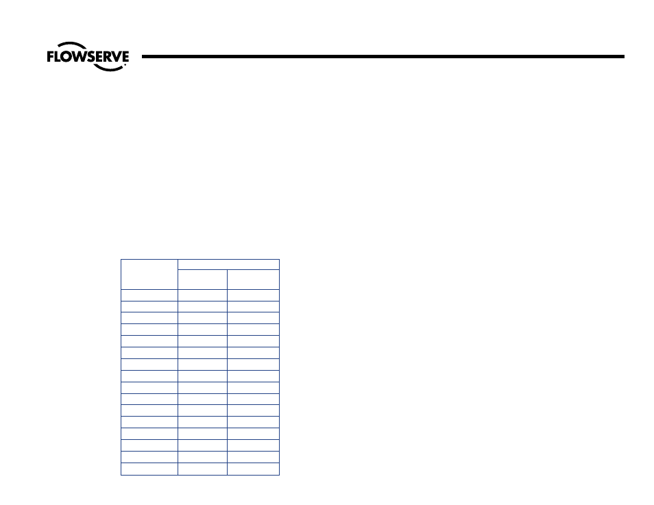
The bolting should be tightened to the
torque values shown in Table B while the
valve is under full line pressure.
Pressure-Seal Leak
Should the leak fail to stop after tightening,
it must be concluded that there is an imper-
fect pressure-seal, and the valve will have
to be opened for examination. (Note:
Regardless of the cause of failure, opened
pressure-seal bonnets should always be
reassembled with a new gasket. These are
available from stock via Air Express from
Raleigh, North Carolina.) Such a leak may
result from any of the following causes:
1. Incomplete Seal Between Bonnet and
Gasket. An incomplete seal around
the gasket seating surface of the bon-
net (or cover on check valves) may be
caused by corrosion, dirt, chips, or
other foreign matter on the mating sur-
faces of the sealing angle.
2. Incomplete Seal Between Body I.D.
and Gasket. An incomplete seal in
the area of the gasket and body I.D.
contact may be caused by surface
imperfections in the body wall in the
form of pin holes, extended cracks, or
indentations where the metal has
failed sometime after valve installation
and use. Such imperfections may be
surface indications of deeper flaws in
the body casting that may cause a by-
pass around the pressure-seal.
Seat and Disk Joint Leak
A leak existing between the seat and disk
of a closed valve might be indicated by
one of the following: a definite pressure
loss in the high-pressure side of the valve;
continued flow through an inspection drain
on the low-pressure side; or, in hot water or
steam lines, a downstream pipe that
remains hot beyond the usual length of time
and conductivity range.
Such a leak may be the result of a distorted
seat caused by uneven welding and stress-
relieving temperatures that were present in
the body when mounting the valve in the
pipe line. It may also develop because of
the operator’s failure to close the valve
tightly. An increased velocity is imparted to
a flow forced through a very small open-
ing. This increased velocity subsequently
gives rise to the “cutting” of both disk and
seat, particularly by particles of line scale
or rust in suspension or normal solids in
solution; or, in spite of the fact that the stel-
lited hard-facing material on the seat and
disk is corrosion and erosion resistant,
grooves, pit marks, or other surface irregu-
larities may be formed on the seat and disk
joint surfaces when the disk is closed
against a foreign body on the seat. This
sometimes occurs during the initial start-up
of a piping system.
Service Problems
(continued)
Table B
Bonnet/Cover Bolt/Nut Pull-Up
Torques
(With Valve Under Pressure)
REQUIRED TORQUE, FT-LBS
BOLT SIZE
METAL
COMPOSITE
GASKET
GASKET
3/8
18
5
7/16
30
5
1/2
45
7
9/16
68
10
5/8
90
15
3/4
150
25
7/8
240
35
1
370
55
1-1/8
533
80
1-1/4
750
110
1-3/8
1020
150
1-1/2
1200
170
1-5/8
1650
230
1-3/4
2250
320
1-7/8
3000
420
2
3300
460