Area 1 & 2 – Flowserve V-377 R4 Edward Valves User Manual
Page 29
AREA 1 & 2
This procedure describes the method for
removing the operator, either handwheel
or Limitorque type, and yoke assembly
from the valve as a unit.
This procedure should be used to remove
the operator and yoke assembly in order
to gain access for servicing the valve
internals (Area 3), i.e., body, seats, bonnet,
disk, etc. It is not suggested if service is
required on either the operator (Area 1) or
yoke assembly (Area 2) themselves.
It has been arranged in accordance with
the general comments on page 18, and is
specifically referenced in “Method 1.”
Study this carefully.
Before beginning, first determine if the
valve has a revolving or non-revolving
stem. Then determine the bonnet type. For
a review of bonnet types, see pages 4, 5,
6 and 7.
Revolving Stem Valves with
Type I Bonnets
See Illustration No. 20 on page 27.
Due to the construction of Type I bonnets, it is
not practical to remove the yoke without also
removing the bonnet. Therefore, refer to page
19 and use the “Method 2” procedure.
Revolving Stem Valves with
Type II Bonnets
See valve Illustration No. 22 on page
30. See operator Illustration No. 14 on
page 22.
Impactor handwheels used on Type II bon-
nets with revolving stems are not attached
to the yoke (only the stem) and the two,
therefore, cannot be removed as a unit.
Refer to page 19 and use the “Method 2”
procedure.
On Limitorque-operated valves, due to the
construction, it is not possible to remove
the operator and yoke assembly as a unit.
Therefore, refer to page 19 and use the
“Method 2” procedure.
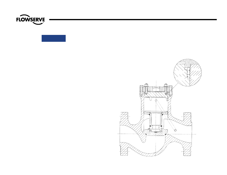
Illustration No. 21
Type I Bonnet on Piston-Lift Check Valve
29
Flow Control Division
Edward Valves
Procedures for Removing Operator and Yoke Assembly as a Unit
GASKET
SPACER
BODY
COVER