Disassembly procedures for bonnet types – Flowserve V-377 R4 Edward Valves User Manual
Page 41
41
Flow Control Division
Edward Valves
bore and lift out the piston, being
careful not to mar any sealing sur-
faces such as the body pressure-seal
area or piston seating surface. Occa-
sionally a vacuum may be formed by
the cooling fluid in the pipe line
below the valve. Until relieved, this
vacuum will prevent removal of the
piston.
25. The bonnet end opening should be
kept covered whenever possible.
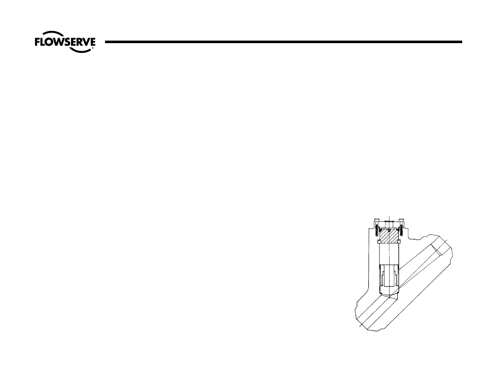
Type IV Pressure-Seal Bonnets –
Piston-Lift Check Valves
See Illustration No. 28.
1. If used, remove the cover/cover
retainer.
2. NOTE: Make certain all pressure is
relieved in the valve body (down-
stream piping). Once the cover
retainer bolts or nuts are completely
removed, the cover/cover retainer
assembly is held against the body
bore only by the friction of the pres-
sure-seal gasket. Trapped pressure
could cause the cover/cover retainer
assembly to be blown out with con-
siderable force. Therefore, care must
be taken to break the cover and pres-
sure-seal gasket loose before the
cover retainer bolts or nuts are com-
pletely removed.
3. Carefully loosen, but do not remove,
the cover retainer bolts or nuts. If
used, loosen the large bolt in the cen-
ter of the cover retainer.
4. Mark the body and cover retainer at
corresponding points for reference
and reassembly.
5. Place a suitable spacer between the
cover retainer and the body. Unless
already equipped, insert a threaded
stud through the center hole of the
cover retainer and thread into the
puller hole in the cover.
6. Place a heavy washer over the stud
to bridge the cover retainer hole and
thread a nut onto the stud. Tighten
the nut (or the large center bolt) until
the pressure-seal gasket and cover is
loose and any pressure is relieved.
7. Remove the cover retainer bolts or
nuts and draw the cover/cover retain-
er assembly out of the body. An eye-
bolt may be inserted in the threaded
cover hole and the assembly lifted
out with a chain hoist, if desired. In
laying the parts aside for inspection,
it is imperative that they be placed
carefully on a bed of rags or other
soft material to avoid marring any
machined surface.
8. Before disassembling the cover/cover
retainer assembly, mark the cover
and pressure-seat gasket at points
(other than sealing surfaces) corre-
sponding to the previous mark on the
cover retainer (see step 4).
9. With a copper or brass drift pin or a
clean hardwood block, tap the gas-
ket retainer to free them in the body
retainer groove. (Note that they can-
not be driven downward in Type IV
construction.)
10. Remove the gasket retainer segments
using two pieces of approximately
3/32 diameter wire bent 90°,half an
inch from the end. Insert the bent end
into the 1/8“ holes provided for this,
removing each segment one at a time.
11. Remove the piston by reaching down
into the body bore and lifting out,
being careful not to mar any sealing
or seating surfaces such as the body
pressure-seal area or piston seating
surface. Occasionally a vacuum may
be formed by the cooling fluid in the
pipeline below the valve. Until
relieved, this vacuum will prevent
removal of the piston.
12. The bonnet end opening should be
kept covered whenever possible.
Disassembly Procedures for Bonnet Types
(continued)
Illustration No. 28
Type IV Bonnet or Piston-Lift Check Valve