General information – Flowserve V-377 R4 Edward Valves User Manual
Page 49
49
Flow Control Division
Edward Valves
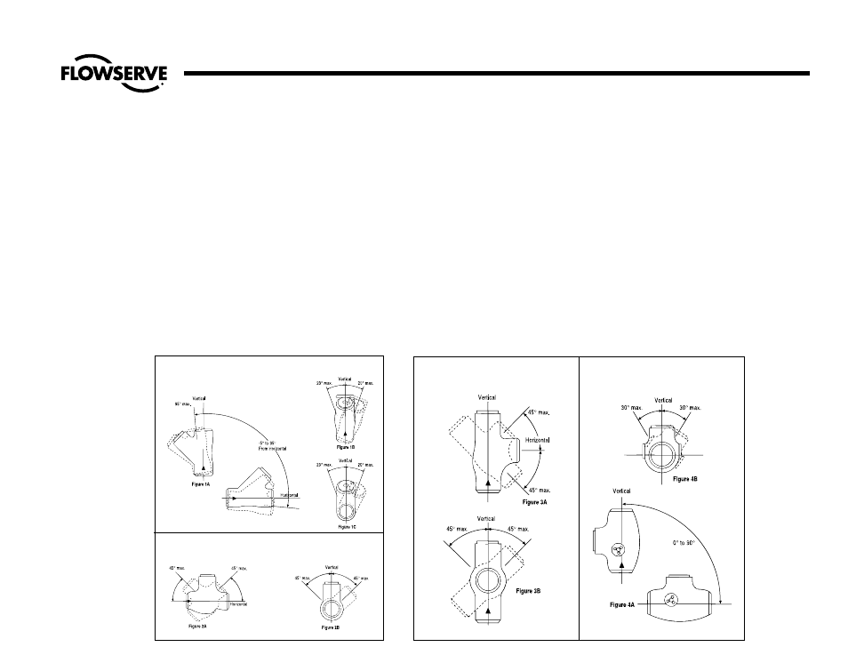
Figure 2
90° Bonnet Piston-Lift Check Valves
Maximum Valve Orientation Limits
Figure 1
45° Inclined Bonnet Piston-Lift Check Valves
Maximum Check Valve Orientation Limits
Figure 3
Angle Piston-Lift Check Valves
Orientation Limits
Figure 4
Tilting Disk Check Valves
Orientation Limits
General Information
Seat and Disk Joint Leaks
A leak existing between the seat and disk
of a closed valve might be indicated by one
of the following: a definite pressure loss in
the high-pressure side of the valve; contin-
ued flow through an inspection drain on the
low-pressure side; or, in hot water or steam
lines, a downstream pipe that remains hot
beyond the usual length of time and con-
ductivity range. Such a leak may by the
result of closing on dirt, scale or other for-
eign matter in the line. It may also develop
because of the operator’s failure to close the
valve tightly. An increased velocity is impart-
ed to a flow forced through a very small
opening. This increased velocity subsequent-
ly gives rise to the “cutting” of both disk
and seat, particularly by particles of line
scale or rust in suspension or normal solids
in solution. In spite of the fact that the hard
surfaced material on the seat and disk is
corrosion and erosion resistant, grooves, pit
marks, or other surface irregularities may be
formed on the seat and disk joint surfaces
when the disk is closed against a foreign
body on the seat. This sometimes occurs
during the initial start up of a piping system.
Leakage of steam through a valve which is
badly steam cut has a whistling or sonorous
sound. If the valve is only slightly steam cut,
however, leakage is identified by subdued
gurgling or weakly popping sounds. These
sounds can be heard through a stethoscope
or by placing one end of a stick against the
valve body while holding the other end
between the teeth, with hands over the ears.
How to Order Parts
During normal working hours, call
800-225-6989 or 919-832-0525. To
assure the correct parts for your valve,
include the valve size, the figure number -
including any prefix and/or suffixes and if
available, the B/M number. All nuclear
valves require the B/M number to properly
identify your valve. This information is locat-
ed on the valve nameplate. The nameplate
is attached to a yoke leg via a cable. If the
nameplate is inaccessible, you can use your
Edward sales drawing; please include the
drawing number as well.