Assembly of composite pressure-seal gaskets, Edward valves, Table c – Flowserve V-377 R4 Edward Valves User Manual
Page 42
42
Flow Control Division
Edward Valves
It is important to determine that the new
composite pressure-seal gasket, the bonnet
and the body sealing area are in satisfac-
tory condition before installation. The fol-
lowing steps will help ensure superior per-
formance of the gasket.
1. Carefully inspect the body bore and
bonnet O.D. sealing surfaces.
Remove any raised metal from the
entry chambers and gasket chamber
regions. Repair any gouges in the
sealing region in accordance with the
instructions on page 10.
2. Inspect the new composite gasket.
Note: All composite gaskets have
cracks and wrinkles in the flexible
graphite. This is a normal result of
the forming process and will not
affect gasket performance.
3. Be sure the anti-extrusion rings are
tightly bonded to the graphitic gas-
ket, so they will not touch the body
during assembly. If any of the anti-
extrusion rings are loose, carefully
scrape away all flexible graphite left
on the anti-extrusion ring surface and
re-bond to the graphite surface using
Loctite 454 or other suitable contact
cement. The ends of the outer rings
should touch after bonding. There
should be an approximate .020 ±
.005” gap at the ends of the inner
ring.
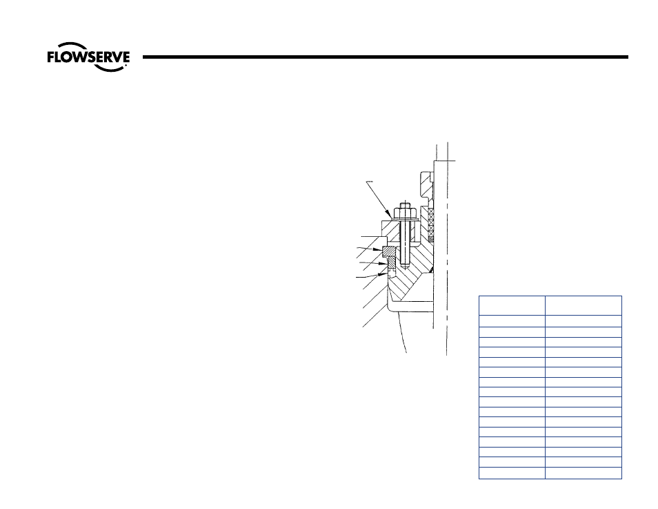
4. Place the gasket on the bonnet with
the two anti-extrusion rings facing up
as shown in the illustration. The gas-
ket should fit snugly around the bon-
net, and the gasket O.D. should not
exceed the O.D. of the bonnet. This
will ensure that the gasket does not
catch on the body and “energize”
prematurely.
5. Install the spacer ring on the bonnet
as shown with the wide end toward
the gasket. Now the valve may be
reassembled using the assembly
procedures described in the following
sections for different types of bonnets,
except that special torqueing
procedures are required as described
in the following:
IMPORTANT: The composite pressure-seal
must remain dry until fully compacted
for proper sealing!
6. Once the bonnet and bonnet retainer
holes have been aligned, lightly lubri-
cate the fasteners with high-tempera-
ture anti-seize lubricant. Assemble the
Belleville washers under the nuts or
capscrews. Assemble remaining parts
as described in previous sections.
7. Preload the bonnet by pulling up with
a well-centered crane load or with
come-alongs.
Assembly of Composite Pressure-Seal Gaskets
BELLEVILLE
WASHERS
GASKET
RETAINER
SPACER
RING
COMPOSITE
GASKET
Table C
Composite Gasket Bonnet/Cover
Bolt/Nut Pull-Up Torques
(For Initial Pull-Up)
Bolt Size
Required Torque
ft.-lbs.
3/8
30
7/16
45
1/2
70
9/16
100
5/8
135
3/4
220
7/8
350
1
540
1-1/8
770
1-1/4
1100
1-3/8
1500
1-1/2
1700
1-5/8
2300
1-3/4
3200
1-7/8
4200
2
4600