Disassembly procedure for yoke assemblies, Area 2 – Flowserve V-377 R4 Edward Valves User Manual
Page 27
AREA 2
This procedure describes the method for:
1) Removing the yoke assembly from the
valve, after the operator has been
removed (procedure described
elsewhere), and
2) Disassembling the yoke assembly itself.
This procedure should be used if service is
required in the yoke assembly itself (Area
2), which includes the yoke and yoke bush-
ing on revolving stem valves, and in addi-
tion, on non-revolving stems, the yoke
bearings and stem guide collar. All of the
following yoke disassembly procedures are
arranged in accordance with the general
comments on page 18. Study these pages
carefully before beginning disassembly.
The following is a step-by-step instruction.
First determine whether the valve to be ser-
viced has a revolving or a non-revolving
stem. Then determine the bonnet type. For
a review of bonnet types, see pages 4, 5,
6 and 7.
Revolving Stem Valves with
Type I Bonnets
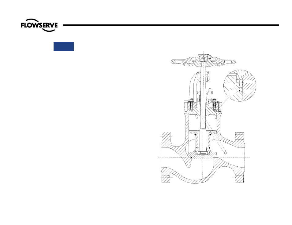
See Illustration No. 20 on this page.
Due to the construction, it is not practical
to remove the yoke assembly separately
(without also removing the bonnet) in Type I
bonnets. In addition, the basic simplicity
minimizes any time savings. Therefore,
remove the operator in accordance with
instructions on pages 19 or 22, and then
refer directly to the procedure for Bonnet
Disassembly, Type 1.
YOKE
GASKET
BODY
BONNET
Illustration No. 20
Type I Bonnet on Stop-Check Valve
27
Flow Control Division
Edward Valves
Disassembly Procedure for Yoke Assemblies
SPACER