Repair procedures, Edward valves, Continued) – Flowserve V-377 R4 Edward Valves User Manual
Page 16: Bonnet or cover repair, Welding rod recommendations
Flow Control Division
Edward Valves
Repair Procedures
(continued)
line scale or other foreign matter that has
inadvertently gotten into the line. Upon dis-
assembly, any body and disk-piston assem-
bly burrs must be removed with emery
cloth, and the bearing surfaces otherwise
made smooth and clean again. Where the
burrs on the piston are very large, it may
be more convenient to chuck the assembly
in an engine lathe and file them off.
Bonnet or Cover Repair
In late 1951 and early 1952 important
changes were made in the pressure-seal gas-
ket design. These changes have greatly
reduced the likelihood of gasket seal leak-
age. In any case of gasket or bonnet leak-
age necessitating repair or replacement, it is
strongly recommended that the valve be con-
verted to the new style by replacing the bon-
net, or cover, and the pressure-seal gasket.
Where foreign matter of any sort is respon-
sible for a gasket seal leak on the outer
angular sealing surface of the bonnet, it is
very likely that it has caused an impression
in this same sealing surface that must be
removed completely before reassembling.
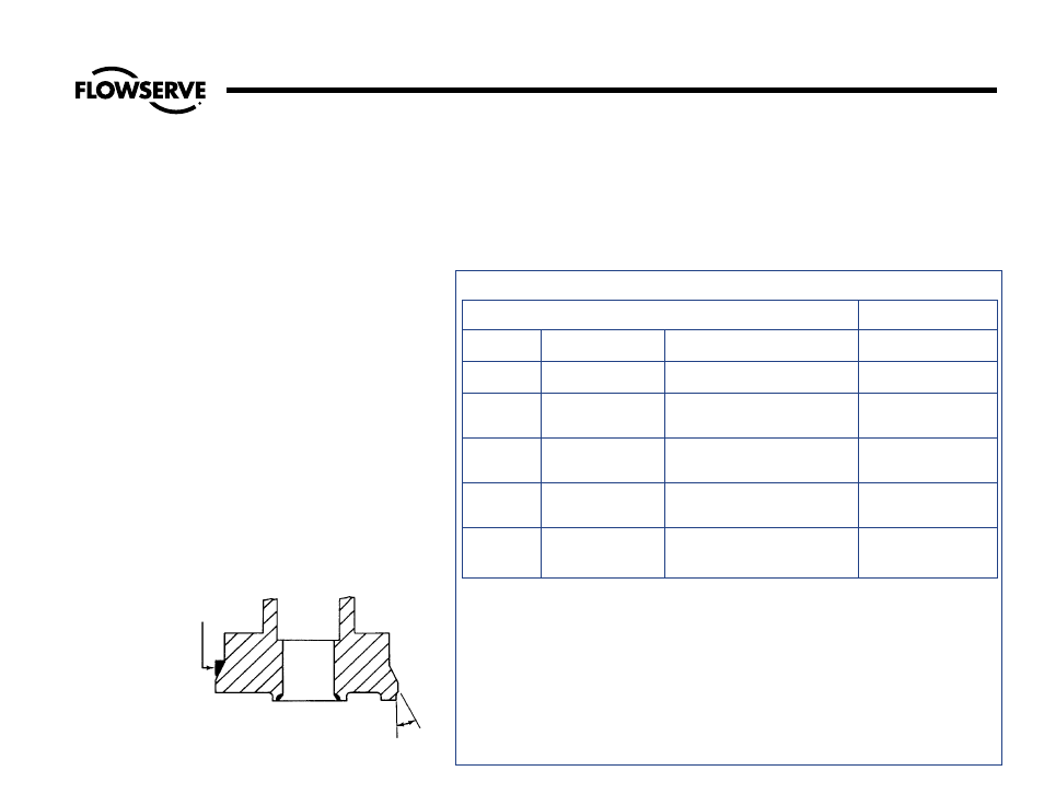
This can be done by taking a shaving or
skin cut on the sealing surface. In so
doing, it is mandatory that the work be
chucked concentric and square to all exist-
ing diameters and surfaces and that the
angle be remachined at 25°, plus 1/2°,
minus 0° as shown in Illustration No. 6.
For old style valves the angle should be
47°, plus 1/2°, minus 0°. When finished,
this surface must be smooth and free from
any marks or surface blemishes, and the
circumferential point where the largest
O.D. meets the angular seal surface must
be lightly honed to remove any sharp
edges or fins.
Welding Rod Recommendations
PRESSURE
SEAL
GASKET
25° +1/2°
–0°
Illustration No. 6
Pressure-Seal Bonnet Seal Angle
Material to be Welded
Weld Rod
Recommendations
ASME IX
Material
ASTM Grade
AWS Classification
P-Numbers
P-1
Carbon Steel
1. ASTM A216, Grade WCB
AWS 5.1
2. ASTM A105
E7018
P-4
1-1/4% Chromium,
1. ASTM A217, Grade WC6
AWS 5.5
1/2% Molybdenum
2. ASTM A182, Grade F11
E8018-B2
Low Alloy Steel
P-5
2-1/4 Chromium,
1. ASTM A217, Grade WC9
AWS 5.5
1% Molybdenum
2. ASTM A182, Grade F22
E9018-B3
Low-Alloy Steel
P-8
18% Chromium,
1. ASTM A351, Grade CF8M
AWS 5.4
8% Nickel
2. ASTM A182, Grade F316
E316
Stainless Steel
P-8
18% Chromium,
1. ASTM A351, Grade CF8C
AWS 5.4
8% Nickel
2. ASTM A182, Grade F347
E347
Stainless Steel
Welding Edward Valves In-Line
When welding a valve in-line, the installer should apply the specific technical rules imposed by the jurisdictional
authority of the area where the valve is installed. In the absence of such rules, following are suggested practices
for welding Edward Valves in-line:
1. Welding should be done using procedures and personnel qualified in accordance with ASME Section IX. Rules
for preheat and postheat are stated in Chapter V of ASME B31.1 (Power Piping).
2. The valve should be welded in-line, one end at a time, in a closed position (approximately a half-turn after the
seat in the body comes in contact with the disk). This is suggested to preclude warpage between seating sur-
faces caused by temperature-induced stresses during welding or subsequent heat treat. It also protects the seat
from weld spatter that might coat the lapped seat and disk. When post-weld heat treat is required, each weld
end should be heat-treated one at a time, to minimize impact of heat on valve internals. Do not heat treat an
Edward Valve with a piping attached as a unit in a furnace, as warpage of parts may occur. After welding,
open the valve and flush the line to clean out all foreign matter.
16