3 optional valtek rotary mounting procedure – Flowserve 3200MD User Manual
Page 10
User Instructions - Digital Positioner 3200MD LGENIM0059-09 12/13
10
The pin should extend approximately
1
⁄
16
" past the take-off arm.
When properly adjusted, securely tighten the bracketing bolts.
Orienting the Take-off Arm for Final Lock Down
1. Tube the Logix 3200MD positioner to the actuator according
to the instructions given in Section 5.5, “Tubing Positioner to
Actuator.”
2. With supply pressure off, rotate the follower arm in the same
direction the shaft would rotate upon a loss of supply pressure.
When the mechanical stop of the follower arm (positioner) is
reached, rotate back approximately 15 degrees.
3. Hold the take-off arm in place; tighten the screw of the take-off
arm.
!
NOTE: The take-off arm should be snug enough to hold the
follower arm in place but allow movement when pushed.
4. Connect regulated air supply to appropriate port in manifold.
5. Remove main cover and locate DIP switches and QUICK-CAL
button.
6. Refer to sticker on main board cover and set DIP switches
accordingly. (A more detailed explanation of the DIP switch
settings is given in Section 7, “Startup.”)
7. Press the QUICK-CAL button for three to four seconds or
until the positioner begins to move. The positioner will now
perform a stroke calibration.
8. If the calibration was successful the green LED will blink GGGG
or GGGY and the valve will be in control mode. Continue with
step 9. If calibration failed, as indicated by a RGGY blink code,
the A/D feedback values were exceeded and the arm must be
adjusted away from the positioners limits. Return to step 2 and
rotate the arm back approximately 10 degrees.
!
NOTE: Remember to remove the air supply before re-adjusting
take-off arm.
9. Tighten the nut on the take-off arm. The socket head screw of
the take-off arm must be tight, about 40 in-lb.
!
NOTE: If the take-off arm slips, the positioner must be
recalibrated.
WARNING: Failure to follow this procedure will result in
positioner and/or linkage damage. Check air-action and
stroke carefully before lockdown of take-off arm to spline
lever adapter.
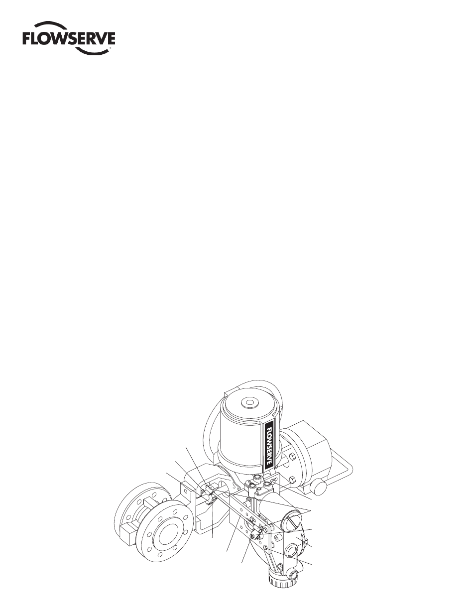
5.3 Optional Valtek Rotary
Mounting Procedure
(See Figure 5)
The optional rotary mounting applies to Valtek valve/actuator assem-
blies that are equipped with mounted volume tanks or handwheels.
The optional mounting uses a four-bar linkage coupled to the valve
shaft. The following tools are required:
•
3
⁄
8
" open-end wrench
•
7
⁄
16
" open-end wrench
• ½ " open-end wrench
Figure 5: Optional Rotary Mounting
Tripper
Tripper Clamp
Bolts (2)
Locknuts (2)
Tie Rod*
10-32 Nut
Lock Washer
Bracket Bolts
5
/
16
-18 (2)
Ball Joint Ends
Follower Arm
Rotate Positioner 90°
Mounting Bolts ¼-20 (4)
* Tie Rod must be cut to desired length.
Valte
k