4 spool valve, 5 spool valve cover – Flowserve 3200MD User Manual
Page 24
User Instructions - Digital Positioner 3200MD LGENIM0059-09 12/13
24
8. Once the regulator pressure is set, tighten the set screw retain-
ing nut on the top of the regulator, remove the air supply to the
positioner, remove the barbed tee, and reconnect the fl exible
tubing from the regulator to the barbed fi tting on the side of the
driver module.
9. Install the plastic board cover. Insert the three retaining screws
through the plastic cover into the threaded boss and tighten
evenly, using a Phillips screwdriver. Do not overtighten (See
Figure 15).
10. Reinstall all covers.
8.4 Spool Valve
The spool valve routes the supply air to one side of the actuator
while venting the opposite side (See Figure 1). The position of the
spool valve is controlled by the driver module.
Replacing the Spool Valve
To replace the spool valve, refer to Figures 12, 14 and 25 and pro-
ceed as outlined below. The following tools are required:
• Phillips screwdriver
1. Make sure the valve is bypassed or in a safe condition.
2. Disconnect the power and air supply to the unit.
3. Remove the spool valve cover by removing the screw and sliding
the cover assembly backwards until the tab is clear of the slot.
It is not necessary to remove the sheet metal cap, hydrophobic
fi lter, or O-ring from this assembly (Figure 14).
WARNING: The spool (extending from the driver module
assembly) is easily damaged. Use extreme caution when
handling spool and spool valve block. Do not handle the
spool by the machined portions of spool. The tolerances
between the block and spool are extremely tight. Contami-
nation in the block or on the spool may cause the spool to
hang.
4. Remove the spool valve block by removing the two Phillips-head
screws and carefully sliding the block off the spool (Figure 12).
5. Carefully remove spool by sliding end of spool out of connecting
clip. Excessive force may bend the spool.
6. Verify that the three O-rings are in the counterbores on the ma-
chined platform where the new spool valve block is to be placed
(Figure 25).
7. Carefully slide the spool into the connecting clip of the driver
module assembly.
8. Carefully slide the block over the spool, using the machined
surface of the housing base as a register (Figure 12). Slide the
block toward the driver module until the two retaining holes line
up with the threaded holes in the base.
9. Install two spool valve screws and tighten securely with a Phil-
lips screwdriver (See Figure 13).
10. Slide the spool valve cover assembly over the spool valve until
the tang engages into the housing slot. Install the spool valve
cover screw and tighten securely (See Figure 12).
11. Reconnect power and air supply to the positioner and perform a
stroke calibration.
8.5 Spool Valve Cover
The spool valve cover incorporates a coalescing fi lter element in a
two-piece cover. This protects the spool valve chamber from dirt and
moisture and provides a low back pressure vent for exhaust air from
the spool valve.
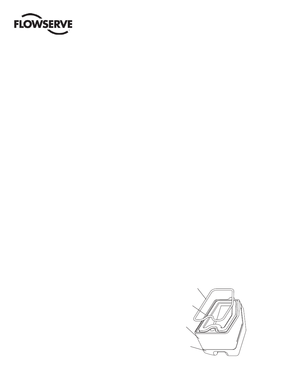
Replacing Filter in Spool Valve Cover
To replace the fi lter in the spool valve cover, refer to Figures 12 and
17 and proceed as outlined below. The following tools are required:
• Phillips screwdriver
1. Remove the spool cover by removing the screw and sliding the
cover assembly backwards until the tab is clear of the slot. The
sheet metal cover may be removed and cleaned with a brush or
by blowing out with compressed air (Figure 12).
2. Remove the O-ring from around the hydrophobic fi lter element
and set aside (Figure 17).
3. Remove the molded fi lter element by pulling it straight out of the
chamber cover vent piece.
4. Install O-ring into base of chamber cover vent piece as shown in
Figure 17.
5. Place new molded fi lter element into the chamber cover vent
piece. This fi lter element provides part of the track to secure the
O-ring installed in the last step.
6. Place spool valve shroud onto spool valve cover.
7. Place the spool valve cover assembly in place by setting it on
the ramp and sliding it until the tab seats in the slot (Figures 12
and 17) and secure with a 8-32 screw.
Figure 17: Spool Valve Cover Assembly
O-ring
Hydrophobic
Filter
Spool
Valve
Cover
Spool
Valve Shroud