7 startup, 5 intrinsically safe barriers, 2 initial dip switch settings – Flowserve 3200MD User Manual
Page 14: 3 operation of confi guration dip switch settings
User Instructions - Digital Positioner 3200MD LGENIM0059-09 12/13
14
In order to calculate the maximum network capacitance, use the
following formula:
C
network
(μF)
≤
- 0.0032
Example:
R
barrier
= 300
Ω
R
wire
= 50
Ω
C
cable
= =
- 0.0032 = 0.08 μF = C
max network
(μf)
=
Maximum Cable Length
Maximum Cable Length
=
= 3636 ft.
65
(R
barrier
+ R
wire
+ 390)
65
(300 + 50 + 390)
22 pF
foot
0.000022 μF
foot
C
max network
(μF)
C
cable
0.08 μF
0.000022 μF/foot
Equation 2
C
network
(μF)
≤
- 0.0032
Example:
R
barrier
= 300
Ω
R
wire
= 50
Ω
C
cable
= =
- 0.0032 = 0.08 μF = C
max network
(μf)
=
Maximum Cable Length
Maximum Cable Length
=
= 3636 ft.
65
(R
barrier
+ R
wire
+ 390)
65
(300 + 50 + 390)
22 pF
foot
0.000022 μF
foot
C
max network
(μF)
C
cable
0.08 μF
0.000022 μF/foot
To control cable resistance, 24 AWG cable should be used for runs
less than 5000 feet. For cable runs longer than 5000 feet, 20 AWG
cable should be used.
6.5 Intrinsically Safe Barriers
When selecting an intrinsically safe barrier, make sure the barrier is
HART compatible. Although the barrier will pass the loop current and
allow normal positioner control, if not compatible, it may prevent
HART communication.
7 Startup
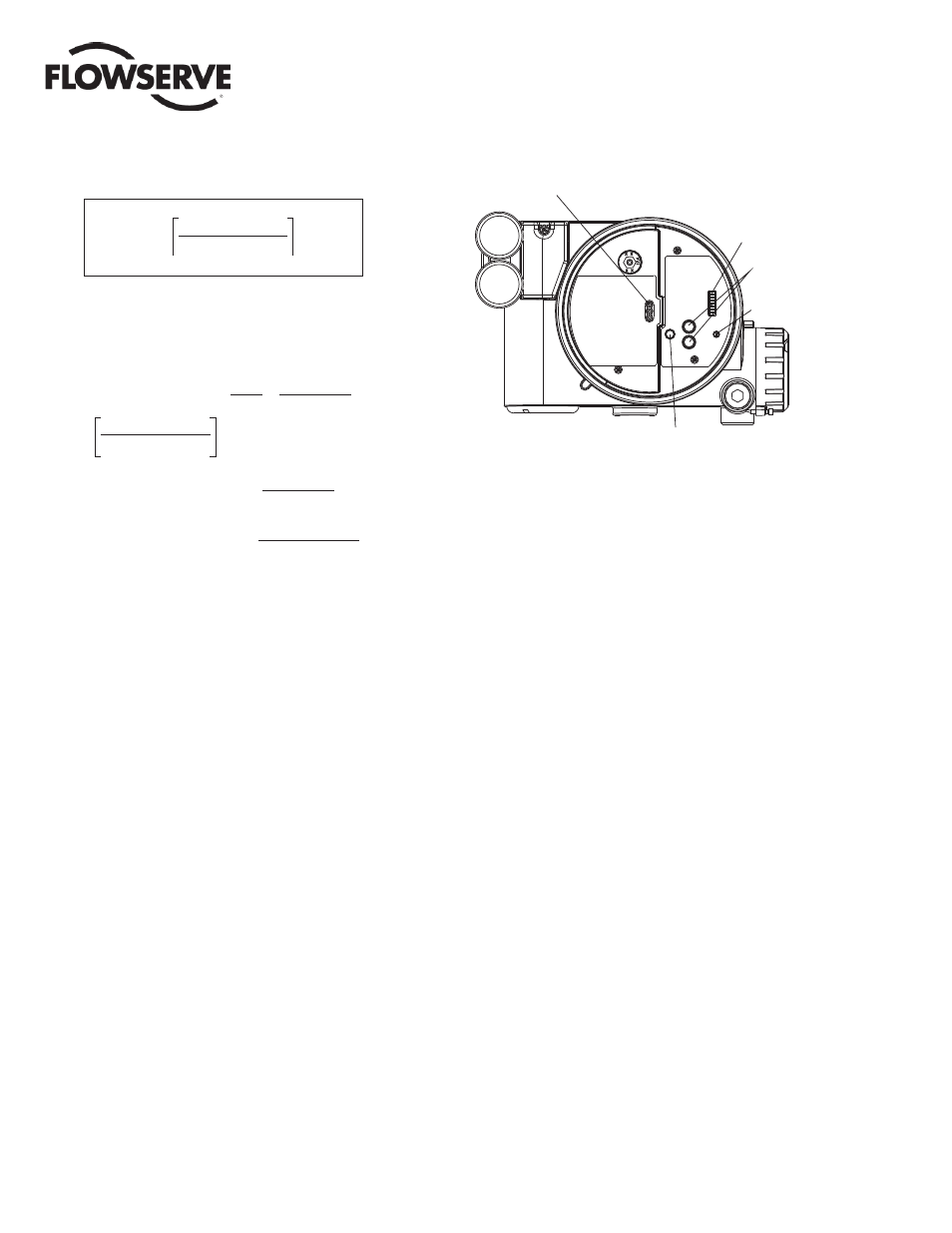
7.1 Logix 3200MD Local Interface
Operation
The Logix 3200MD local user interface allows the user to confi gure
the basic operation of the positioner, tune the response, and calibrate
the positioner without additional tools or confi gurators. The Local
interface consists of a quick calibration button for automatic zero
and span setting, along with two jog buttons for spanning valve/
actuators with no fi xed internal stop in the open position. There is
also a switch block containing 8 switches. Six of the switches are
for basic confi guration settings and one is for calibration options.
There is also a gain selector switch for adjusting the positioner gain
settings. For indication of the operational status or alarm conditions
there are also 3 LEDs on the local user interface.
Figure 8: Local User Interface
LEDs
DIP Switch Block
Jog Buttons
Rotary
Selector
Switch
QUICK-CAL Button
7.2 Initial DIP Switch Settings
Before placing the unit in service, set the dip-switches in the Confi g-
uration and Cal boxes to the desired control options. For a detailed
description of each dip-switch setting, See Sections 1&2.
!
NOTE: The switch settings in the Confi guration box are activated
only by pressing the “Quick Cal” button, except Auto-tune adjust-
ments that can be made at any time.
7.3 Operation of Confi guration
DIP Switch Settings
The fi rst 7 Dip Switches are for basic confi guration
Air Action
This must be set to match the confi guration of the valve/actuator
mechanical tubing connection and spring location since these deter-
mine the air action of the system.
ATO (air-to-open) Select ATO if increasing output pressure from
the positioner port 1 is tubed so it will cause the valve to open.
ATC (air-to-close) Select ATC if increasing output pressure from
the positioner port 1 is tubed so it will cause the valve to close.
Signal at Closed
Normally this will be set to 4 mA for an Air-to-open actuator, and
20 mA for an Air-to-close actuator confi guration.
4 mA Selecting 4 mA will make the valve fully closed when the
signal is 4 mA and fully open when the signal is 20 mA.
20 mA Selecting 20 mA will make the valve fully closed when
the signal is 20 mA and fully open when the signal is 4 mA.