9optional hardware, 1 vented design, 2 hart modem – Flowserve 3200MD User Manual
Page 28
User Instructions - Digital Positioner 3200MD LGENIM0059-09 12/13
28
9
Optional Hardware
9.1 Vented Design
(See Figures 19 and 20)
A standard Logix 3200MD positioner is vented directly to the atmo-
sphere. When supply air is substituted with sweet natural gas, piping
must be used to route the exhausted natural gas to a safe environ-
ment. This piping system may cause some positioner back pressure
in the main chamber (from the modulator and regulator) and spool
chamber (from the actuator). Back pressure limitations are described
below.
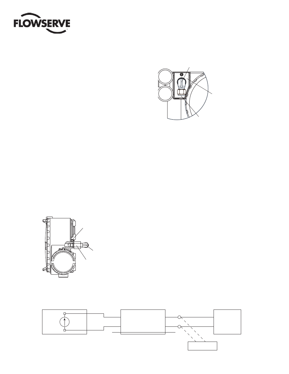
Two chambers must be vented on the Logix 3200MD positioners:
the main housing chamber and the spool valve chamber (Figures 19
and 20). The main chamber vent is located on the backside of the
positioner (See Figure 19). Vented-design Logix 3200MD position-
ers are supplied from the factory with a fi tting installed in the main
chamber vent. Connect the necessary tubing/piping to this fi tting to
route the exhausted natural gas to a safe environment.
The maximum allowable back pressure from the collection device on
the main housing vent is 2.0 psig (0.14 barg). Vent fl ow rate is 0.5
std ft
3
/min (1.4 std liter/min).
WARNING: The back pressure in the main housing must
never rise above 2.0 psig (0.14 barg).
Figure 19: Main Housing Vent
Maximum Allowable
Housing
Back Pressure
2.0 psig (0.14 barg)
¼" NPT x ¼"
Swagelok Tube Fitting
¼" FNPT x "
NPT Reducer
1
⁄
8
Figure 20: Spool Cover Vent
Maximum Allowable
Spool Back Pressure
8 psig (0.55 barg)
Customer Connection
Tubing
3
⁄
8
"
NPT x Swagelok
Tube Fitting
3
⁄
8
"
3
⁄
8
"
The spool valve chamber (See Figure 20) must also be vented
through the spool valve cover. Vented-design Logix 3200MD
positioners are supplied from the factory with a fi tting installed in
the spool valve cover (item SKU 179477). Connect the necessary
tubing/piping to this fi tting to route the exhausted natural gas to
a safe environment. The maximum allowable back pressure in the
spool valve chamber is 8 psig (0.55 barg). Pressures greater than 8
psig will cause vented gas to leak past the spool cover O-ring to the
atmosphere and will result in overshoot of the positioner.
9.2 HART Modem
The HART modem is a device that connects to the serial com-
munications port of a computer. This modem converts the RS-232
COM port signals to the HART signal. A HART modem is optional in
ValveSight since a MUX can be used in its place. The HART modem
takes power from the RS-232 COM port lines. If using a laptop
computer running on an internal battery, HART communication may
become erratic as the batteries begin to lose charge. This is due to
a reduction in HART modem power. Allow batteries to recharge or
apply AC adapter power to the laptop to correct the problem. A HART
modem is available through your Flowserve representative. (Please
refer to Section 12 for part numbers.)
When using a HART modem with ValveSight or when using the
HART 375 handheld, the leads can be connected anywhere across
the 4-20 mA current signal. The leads are not polarity sensitive.
When using a fi lter, the connection must be made between the fi lter
output and the Logix 3200MD (See Figure 22).
+
-
+
-
+
-
C
D
F
E
G, H
A, B
DCS
LOGIX
HART Connection
FILTER
Drain Wire
4-20 mA
Current Source
Logix
32XXIQ
Figure 21: HART VHF Filter Schematic