6 stem position sensor – Flowserve 3200MD User Manual
Page 25
User Instructions - Digital Positioner 3200MD LGENIM0059-09 12/13
25
8.6 Stem Position Sensor
The position feedback assembly transmits valve positions informa-
tion to the processor. This is accomplished by means of a rotary
position sensor that connects to the valve stem through a feedback
linkage. To provide for accurate tracking of the pin in the slot, the
follower arm is biased against one side of the slot with a rotary
spring. This spring also automatically moves the position feedback
assembly to its limit in the unlikely event of failure of any component
in the linkage.
Stem Position Sensor Replacement
To replace the stem position sensor, refer to Figure 15, 18 and 25
and proceed as outlined below. The following tools are required:
• Phillips screwdriver
WARNING: Observe precautions for handling electrostati-
cally sensitive devices.
1. Make sure the valve is bypassed or in a safe condition.
2. Disconnect the power and air supply to the unit.
3. Remove the main cover.
4. Remove the plastic board cover by removing the three retaining
screws (See Figure 15).
5. Disconnect the position sensor wires from the main PCB
assembly.
6. Remove the two rotary position sensor-retaining screws and lift
the sensor out of the housing.
7. Turn the new position sensor shaft until the dot on the side of
the shaft is aligned with the wires on the side of the position
sensor (Figure 18).
8. Insert the position sensor into the shaft with the wires pointing
toward the main PCB assembly. Turn the position sensor clock-
wise until bolting slots align with the housing screw holes and
the wires on the sensor protrude over the main PCB assembly.
!
NOTE: Do not mix the position sensor with those from older
Logix positioners. Older models contain sensors with different
ranges that will not work in the Logix 3200MD model. The wires
on the Logix 3200MD position sensor are red, white and black.
9. Carefully center the position sensor on the shaft bore, insert and
tighten the screws. Do not overtighten.
10. Route the wires along the side of the position sensor and recon-
nect to the main PCB assembly.
11. Install the plastic board cover. Insert the three retaining screws through
the plastic cover into the threaded boss and tighten evenly, using a
Phillips screwdriver. Do not overtighten (See Figure 15).
12. Reinstall all covers.
13. Reconnect power and air supply to the positioner and perform a
stroke calibration.
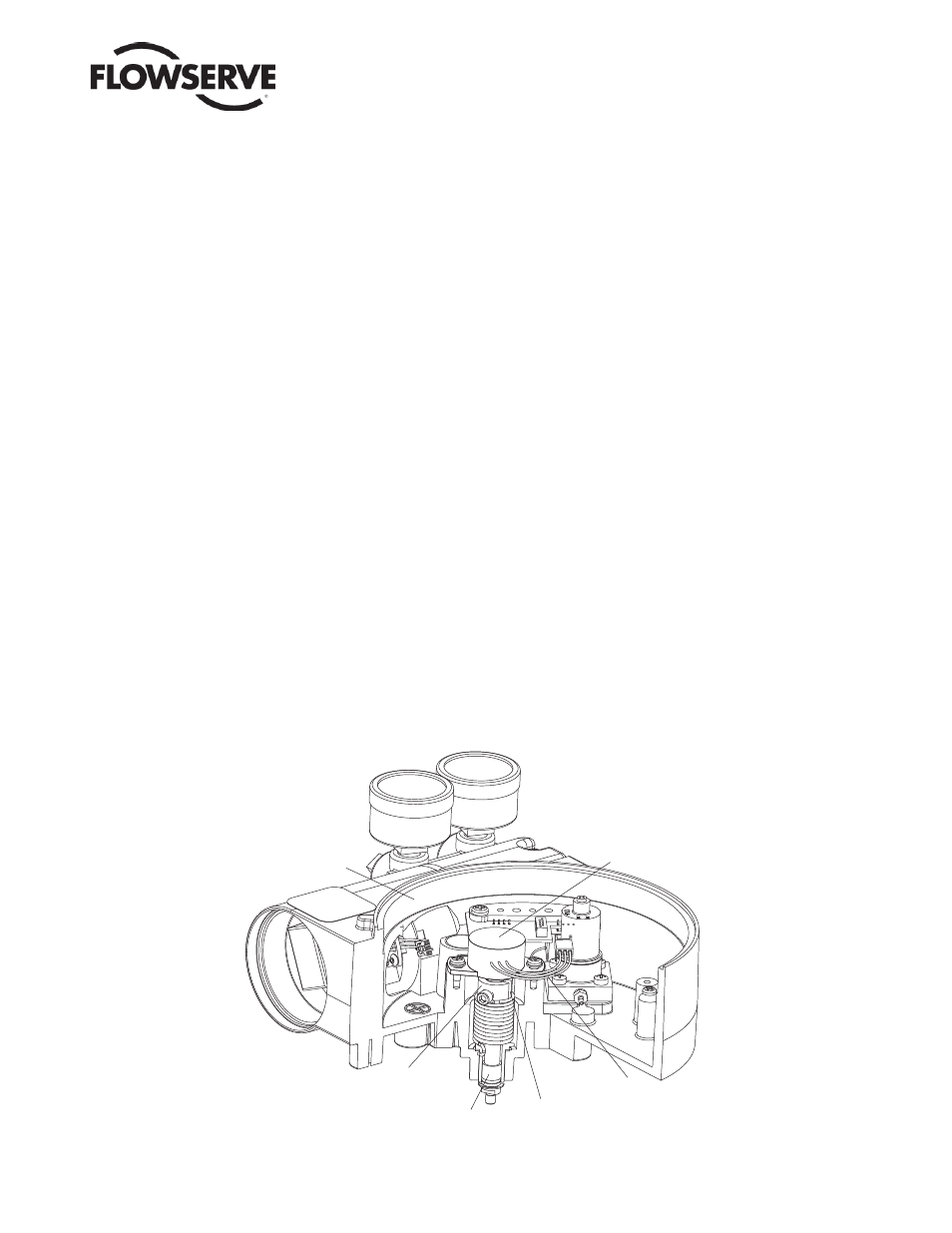
Stem Position
Sensor Dot
Bearing
Feedback
Shaft
Sensor
Cable
Stem
Position
Sensor
Housing
Figure 18: Stem Position Sensor Orientation