8maintenance and repair, 1 driver module assembly – Flowserve 3200MD User Manual
Page 21
User Instructions - Digital Positioner 3200MD LGENIM0059-09 12/13
21
8
Maintenance and Repair
8.1 Driver Module Assembly
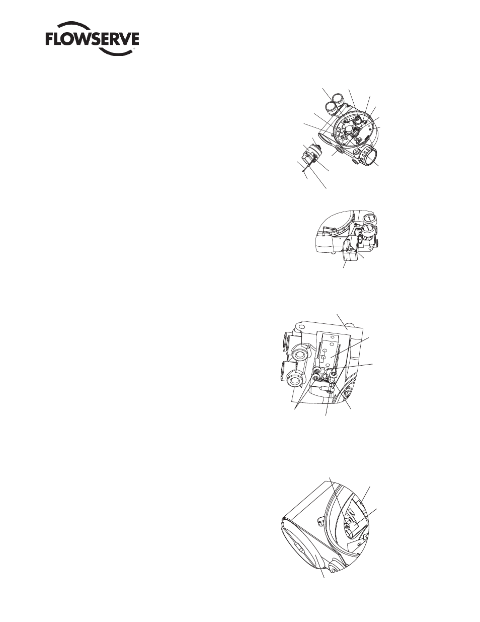
The driver module assembly moves the spool valve by means
of a differential pressure across its diaphragm. Air is routed to
the driver module from the regulator through a fl exible hose. A
barbed fi tting connects the fl exible hose to the driver module
assembly. Wires from the driver module assembly connect the
hall effect sensor and the piezo valve modulator to the main PCB
assembly.
Driver Module Assembly Replacement
To replace the driver module assembly, refer to Figures 11-15 and 25
and proceed as outlined below. The following tools are required:
• Flat plate or bar about
1
⁄
8
" thick
• Phillips screwdriver
• ¼ " nutdriver
WARNING: Observe precautions for handling electrostatically
sensitive devices.
1. Make sure the valve is bypassed or in a safe condition.
2. Disconnect the power and air supply to the unit.
3. Remove the driver module cover (Figure 14), using a fl at bar or
plate in the slot to turn the cover.
4. Remove the spool valve cover by removing the screw and slid-
ing the cover assembly backwards until the tab is clear of the
slot (Figure 12). The sheet metal cap, hydrophobic fi lter, and
O-ring should be removed with the spool valve cover. It is not
necessary to take these parts out of the spool valve cover.
5. Being careful not to lose the nylon washer, remove the Phillips-
head screw that attaches the driver module to the main housing
(Figure 13).
WARNING: Spool (extending from the driver module
assembly) is easily damaged. Use extreme caution when
handling spool and spool valve block. Do not handle the
spool by the machined portions of spool. The tolerances
between the block and spool are extremely tight. Contami-
nation in the block or on the spool may cause the spool to
hang.
6. Remove the spool valve block by removing the two Phillips-head
screws and carefully sliding the block off the spool (Figure 13).
7. Carefully remove the spool by sliding the end of the spool out of
the connection clip. Excessive force may bend spool.
8. Remove the main cover.
Figure 11: Driver Module Assembly
Figure 12: Spool Valve Cover Assembly
Screw
Spool Valve Cover
Pressure Sensor Board
Hall Sensor
Connection
Pressure
Modulator
Connection
O-ring
Driver Module
Assembly
Analog
Output
Board
Connection
Analog
Output Board
Install Barbed Fitting after
Driver Module is in housing
Hall Sensor Connector
Pressure Modulator Connector
Position wires
to the rear
of Modulator
Regulator
Pressure Sensor
Board Connection
User Interface
Board Connection
Stem Position
Sensor
Connection
Main PCB
Retaining
Screw
Spool Valve
Screw
Nylon
Gasket
Driver to
Housing Screw
Spool
Spool
Valve
Block
Housing
Figure 13: Spool and Block
Barbed Fitting
Flat on
Housing
Flat on
Driver
Module
Driver Module Cover
Figure 14: Driver Module Barbed Fitting