Flowserve 2000 Series Digital Positioner User Manual
Page 10
42-10
Flowserve Corporation, Valtek Control Products, Tel. USA 801 489 8611
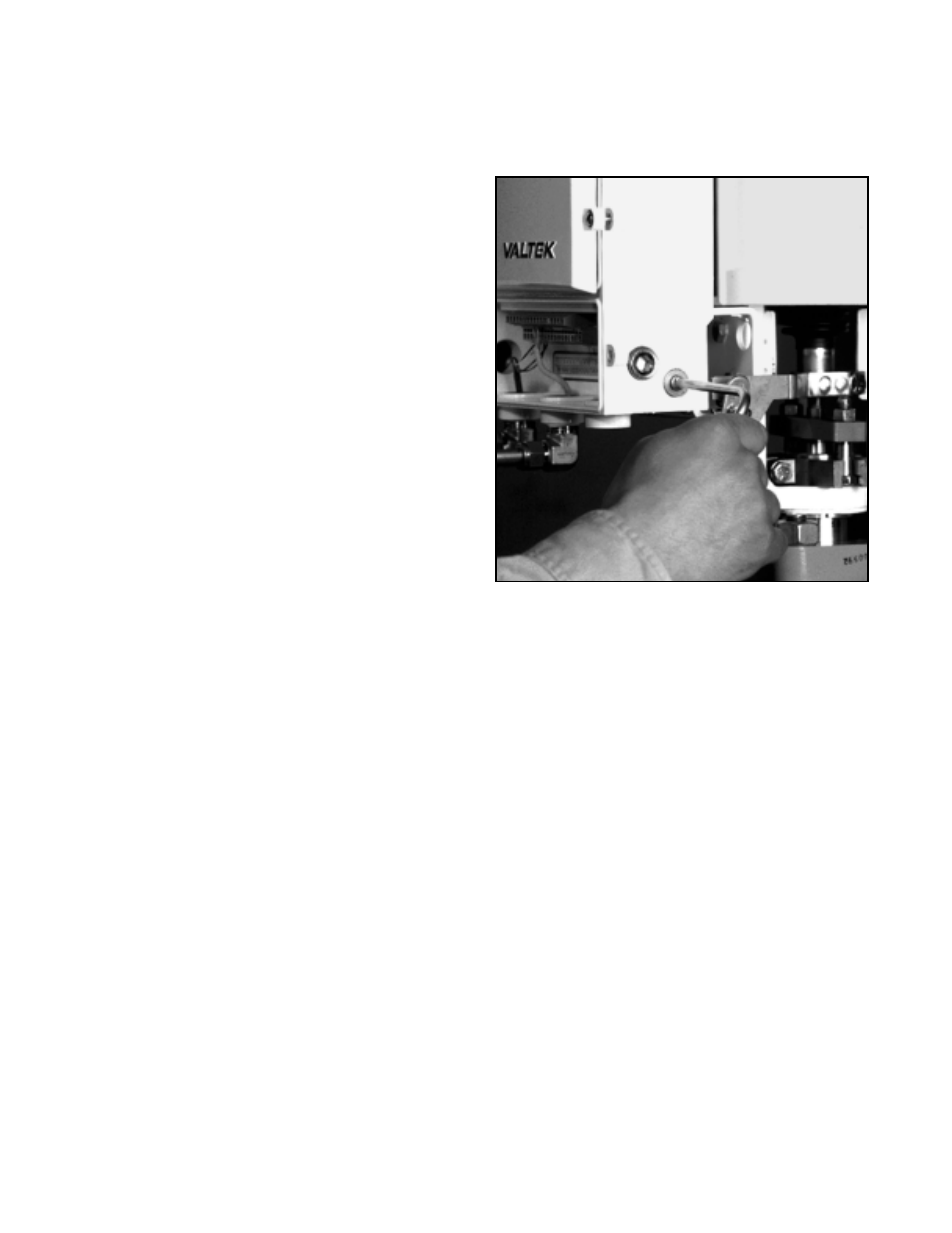
Keypad Assembly Replacement
If, after consulting with the local Valtek or factory repre-
sentative, the StarPac II / Logix 2000's keypad is found
to be defective and needs replacement, refer to Figure
3 and proceed as follows.
1. Make sure valve is by-passed and in a safe condition.
2. Disconnect the power and air supply to the unit.
3. Undo the two captive screws securing the upper
door to the housing and open the upper door.
4. Undo the two screws securing the inner door to the
housing and swing the inner door completely open.
5. Carefully disconnect the keypad connector from the
board stack.
6. Remove the four hinge mounting screws and re-
move the inner door.
7. Install the new keypad assembly in reverse order.
Note: When installing a new keypad assembly,
check for proper door alignment before final lock-
down of hinge-mounting screws.
Feedback Assembly Replacement
If it is determined that the Feedback Assembly needs
replacement, refer to Figures 3 and 9 then proceed as
follows: (New feedback assembly is preset at the factory.)
1. Make sure valve is by-passed or in a safe condition.
2. Disconnect the power and air supply to the unit.
3. Disconnect the positioner pin and follower arm from
the feedback shaft.
4. Remove the four feedback cover screws and
remove the cover.
5. Disconnect the three-pin connector from the hallpot
while observing the connector orientation.
6. Remove the two potentiometer bracket screws.
7. Remove the retaining ring from the feedback shaft.
8. Thread the feedback shaft tool (provided in the
replacement kit) onto feedback shaft and push
shaft out of bushing (refer to Figure 9).
9. Remove feedback shaft tool and feedback assembly.
10. To install the new feedback assembly, lightly grease
the feedback shaft and apply thread locking com-
pound to the two potentiometer bracket mounting
holes. Slide the feedback assembly into the feed-
back bushing.
11. Thread on the feedback shaft tool and push while
turning clockwise, aligning the stroke-stop screw
and stop boss. Next, pull back to the seat stop on
the housing (refer to Figure 9).
12. Remove the feedback shaft tool and install the
retaining ring in the feedback shaft.
13. Using two mounting screws, fasten the potentiometer
bracket to the housing, making sure the feedback
assembly is aligned and the flex couple is engaged.
14. Reconnect the three-pin connector to the hallpot (in
orientation as noted above).
15. Replace the feedback cover and four cover screws.
Then perform a stroke calibration.
Figure 9: Feedback Shaft Tool
Regulator Filter Replacement
To replace the regulator filter, refer to Figures 3 and 10
then proceed as follows:
1. Make sure valve is by-passed or in a safe condition.
2. Disconnect the power and air supply to the unit.
3. Remove the four driver module cover screws and
set the cover aside.
4. Disconnect the four-pin connector from the T-board,
observing the connector orientation.
5. Remove the four driver module mounting screws
and remove the driver module.
6. Carefully remove the pilot valve gasket by peeling
or scraping.
7. Remove the old regulator filter and insert the new
filter (refer to Figure 10).
8. Remove the backing on the pilot valve gasket to
expose the adhesive and apply the pilot valve
gasket to the housing, making sure that the holes
are aligned.
9. Apply thread locking compound to the four mount-
ing holes and fasten the driver module to the hous-
ing with the four mounting screws.
10. Reconnect the four-pin connector to the T-board in
the orientation as noted above.
11. Replace the driver module cover with the four cover
screws.