Flowserve 2000 Series Digital Positioner User Manual
Page 11
42-11
Flowserve Corporation, Valtek Control Products, Tel. USA 801 489 8611
13. Apply thread locking compound to the four mount-
ing holes and fasten the driver module to the hous-
ing using the four mounting screws.
14. Reconnect the four-pin connector to the T-board in
the same orientation as noted above.
15. Replace the driver module cover and cover screws.
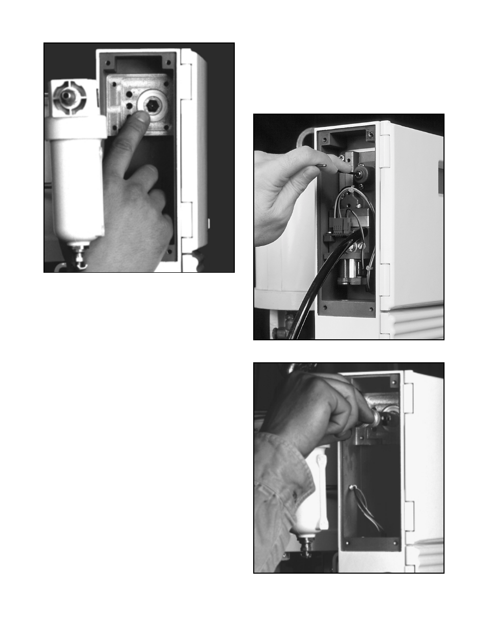
Figure 11: Setting Regulator Pressure
Figure 10: Regulator Filter Replacement
Driver Module Assembly Replacement
To replace the driver module assembly, refer to Figures
3, 10, 11, and 12 then proceed as follows:
1. Make sure valve is by-passed or in a safe condition.
2. Disconnect the power and air supply to the unit.
3. Remove the four driver module cover screws and
set the cover aside.
4. Disconnect the four-pin connector from the T-board,
observing the connector orientation.
5. Remove the four driver module mounting screws
and remove the driver module. (Check the pilot
valve and poppet assemblies for wear or deteriora-
tion. If needed, continue with steps 6-12. If clean-
ing only, refer to Spool Valve Assembly Replace-
ment then proceed to step 13 after cleaning.)
6. Carefully remove the pilot valve gasket by peeling
or scraping.
7. Remove the poppet guide, poppet O-ring, poppet,
and poppet spring.
8. Remove and replace the regulator filter.
9. Insert the new poppet spring into the housing pop-
pet hole.
10. Place the O-ring on the poppet seat.
11. Thread the poppet guide and poppet into the hous-
ing and tighten to 6-inch/lbs. maximum (refer to
Figure 12).
12. Remove the backing from the pilot valve gasket to
expose the adhesive and apply the gasket to the
housing, making sure the holes are aligned.
Figure 12: Poppet Guide Installation