Figure 4: user interface terminal pinouts, Table i: user interface terminal connections – Flowserve 2000 Series Digital Positioner User Manual
Page 5
42-5
Flowserve Corporation, Valtek Control Products, Tel. USA 801 489 8611
P
1
Grnd (Blk)
P
2
Grnd (Blk)
P
1
out - (Wht)
P
2
out - (Wht)
P
1
out + (Grn)
P
2
out + (Grn)
P
1
+5 VDC (Red)
P
2
+5 VDC (Red)
Thrm Coup (Yel)
Analog
2
in -
Thrm Coup (Red)
Analog
2
in +
Analog
2
out -
Analog
1
in -
Analog
2
out +
Analog
1
in +
Analog
1
out -
Spare
Analog
1
out +
Pulse Out
Spare
Pulse Out
Com B -
Alarm Contact
Com B +
Alarm Contact
Com A -
Discrete 2 in
Com A +
Discrete 2 in
24 VDC -
Discrete 1 in
24 VDC +
Discrete 1 in
Com A +
Com A -
1
2
3
4
5
6
7
8
9
10
11
12
13
14
15
16
17
18 19 20
21 22
23 24
25 26 27
28 29
30 31 32
33 34
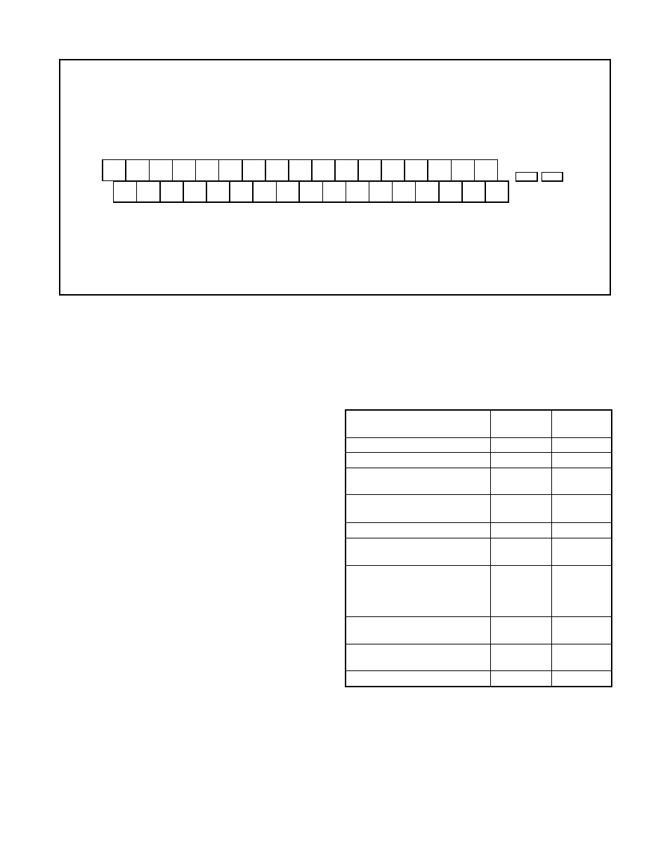
Figure 4: User Interface Terminal Pinouts
• Ensure that the block valves in the process line
around the unit are closed and the process is
diverted around the unit.
Table I:
User Interface Terminal Connections
Signal
Negative
Positive
Term. No.
Term. No.
24 VDC power
16
17
Valve command signal
24
25
Primary RS-485
14
15
communication link
Secondary RS-485
12
13
communication link
Auxiliary input (4-20 mA)
22
23
Analog output (4-20 mA) 1
9
10
Analog output (4-20 mA) 2
7
8
Discrete input 1 – switch/
33
34
solenoid monitoring
(discrete mode source
input)
Discrete input 2 – switch/
31
32
solenoid monitoring
Discrete output 1 (malfunc-
29
30
tion alarm contact)
Discrete output 2 (pulse)
27
28
3. Turn on the 24 VDC power to the unit, and verify that
it has been correctly wired by checking the following:
• 24 VDC power is at least 300 mA and between 18.0
and 64.0 VDC
• Polarity is correct
• Local display is on; if not, check the power supply.
4. Close the front cover on the housing of the unit.
To connect the wiring to the StarPac II / Logix 2000 unit,
refer to Figures 1 and 4, and Table I, then proceed as
follows.
1. Open the lower door on the front of the housing.
WARNING: Do not open the electronic housing
covers in flammable atmospheres; otherwise,
possible injury to personnel or equipment may
occur.
2. Connect the required wires to the terminal interface
block and computer as described in Figure 4 and
Table I. (The system must have 24 VDC power for
operation.)
NOTE: The StarPac II / Logix 2000 unit remembers
the operating mode setting (automatic or manual)
from the last time the unit had power. When power
to the system is turned on again, the unit will resume
operation in the previous mode.
Normally the unit arrives from the factory set in the
manual analog operating mode. This means a
command signal will position the valve the same as
a traditional control valve, providing a plug position
proportional to the 4 - 20 mA signal.
To avoid upsetting the process because of improper
operating mode selection:
• Ensure that the system arrived from factory with
the proper operating mode setting in the shop prior
to installation by connecting air supply and com-
mand signal, then turning on the power and looking
at the mode value on the local display, or;
• Set the proper operating mode for the particular
application in the shop prior to installation by
selecting the desired operating mode from the
local interface or in the Tuning/Tune screen of the
StarTalk software, or;