Position feedback system, Pressure sensor replacement, Figure 6: positioner diagram – Flowserve 2000 Series Digital Positioner User Manual
Page 8
42-8
Flowserve Corporation, Valtek Control Products, Tel. USA 801 489 8611
OO
Position Feedback System
The position feedback linkage of the StarPac II / Logix
2000 system is a critical part of the system. This linkage
is also used in the StarPac II to calculate the valve’s C
V
for a given stroke for flow measurement. This linkage
should be lubricated and checked periodically for tight,
smooth operation. The follower arm should operate
smoothly with no binding and have a positive spring
loading on the arm. Inspect the follower arm pin for
excess wear and replace if needed. The take-off arm
attached to the stem clamp must be firmly secured to
the stem clamp and perpendicular to the actuator stem.
If this takeoff arm is canted or misaligned, problems
may occur with positioner calibration and the position
reading on the unit may go out of range.
On rotary actuators, make sure the adjustment linkage
locknut is tight and has no excessive play in the ball
joints. The rotary shaft clamp must be tight and should
not freely rotate on the shaft.
Pressure Sensor Replacement
Standard StarPac II pressure sensors are typically in-
stalled directly into the control valve body. Before they
can be removed, the process line must be depressurized
and drained of all fluids and the valve decontaminated.
To replace a pressure sensor, refer to Figure 7 then
proceed as follows.
WARNING: The process line must be depressurized
and drained of process fluid, and decontaminated
prior to working on internal valve components. Failure
to do so may cause serious injury to personnel.
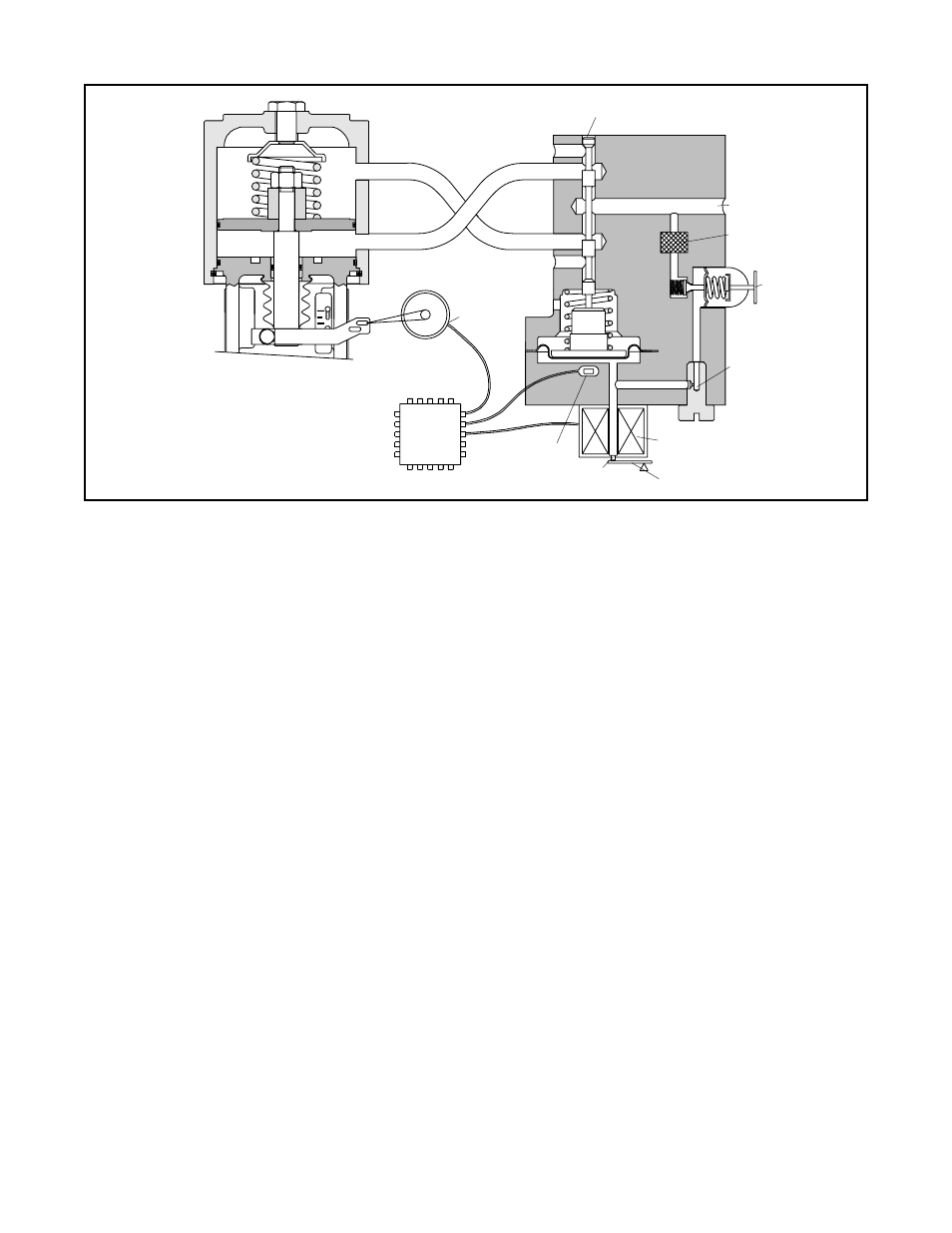
Figure 6: Positioner Diagram
Exhaust
Output 1
Output 2
Exhaust
Stem Position
Sensor
Digital
Position
Algorithm
Air-to-open
Configuration
Spool Position
Sensor
Nozzle
Electromagnetic Coil
Flapper
Pilot Valve Spool
Air Supply
Filter
Regulator
Orifice
signals are not equal, the spool valve will move up (or
down) and, by means of the modulator, will change the
output pressures and flow rate. This will cause the
piston to move until the signal of the feedback sensor
equalizes with the command signal.
The detailed sequence of positioner operations are as
follows: An increase in the command signal forces the
modulator signal capsule and spool valve upward. This
motion of the modulator also pushes the pilot valve
spool upward from its equilibrium position. This opens
the pilot valve ports, supplying air to port one and
exhausting air from port two. This causes the actuator
piston to move upward.
This upward motion of the piston is transmitted back to
the positioner through the feedback linkage and hallpot
sensor signal changing proportionally to the valve posi-
tion. The piston continues to stroke upward until the
signal of the feedback sensor increases sufficiently to
counter the signal being sent to the modulator. At this
point, the spool is at its equilibrium position as the
pressures in the cylinder stabilize and the air flow to the
actuator decreases.
After the piston has reached the required position, the
feedback signal will equal the spool position generated
in the modulator capsule. The computer will then make
small null adjustments to fine-tune the desired position
and compensate for changes in dynamic loading.
A decrease in the command signal reverses the de-
scribed actions causing a proportional downward move-
ment of the actuator piston and stem.