Flowserve 2000 Series Digital Positioner User Manual
Page 9
42-9
Flowserve Corporation, Valtek Control Products, Tel. USA 801 489 8611
7. Align the red dots on the sensor and connector,
and reconnect the Lemo connector. Fully seat the
connector until the locking sleeve latches. Replace
the sensor nut and tighten.
8. Pressurize the valve body to make sure the sensors
are properly seated before attaching the sensor
conduit and tightening.
9. Reattach the conduit lines and securely tighten the
fittings.
Figure 8: Thermocouple Replacement
Thermocouple Replacement
In normal configuration, the thermocouple does not
penetrate the valve body wall. Depressurizing the body
is not necessary when replacing the thermocouple.
NOTE: If the StarPac II was ordered with a special
thermocouple option, verify the need to depressurize
the body before proceeding.
1. Disconnect power and air supply to the unit.
2. Open the lower terminal block cover and discon-
nect the red and yellow thermocouple wire.
3. Loosen the tubing nuts on both ends of the thermo-
couple assembly (refer to Figure 8).
4. Pull the wires out of the StarPac base and slip the
tubing off the wires.
5. Unscrew the old thermocouple from the body.
6. Install the new thermocouple.
7. Feed the wires back through the tubing and into the
StarPac housing.
8. Tighten the tubing nuts.
9. Cut the thermocouple wires to length. Strip and
reattach wires to the terminal block, noting color
polarity. (The red wire is the negative signal.)
10. Check that all the fittings are tight.
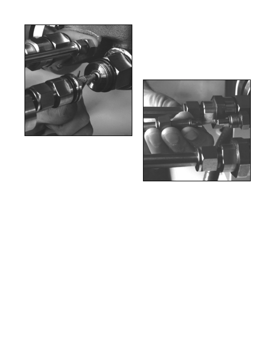
Figure 7: Disconnecting Lemo Connector
WARNING: If the pressure sensors are remote-
mounted, the sensor will be located in a sensor
housing in the tubing line and not in the sensor
housing located on the valve body. This section
of the tubing contains process fluid and must be
drained and decontaminated before the sensor is
removed. The procedure for sensor removal and
replacement will be similar to that outlined below.
(Refer to alternate sensor information when this type of
sensor is included with system.)
1. Depressurize and decontaminate the line and valve.
Loosen the tubing nuts on the conduit leading to the
pressure sensor, if applicable.
2. Loosen the sensor nut.
3. Gently pull the conduit and sensor nut approxi-
mately
1
/
2
to 0.75-inch from the sensor. Use needle
nose pliers to release the locking sleeve of the
Lemo™ connector by moving the collar away from
the sensor and disconnect the connector from the
sensor. Swing the sensor conduit out of the way
(refer to Figure 7).
4. Unscrew the sensor from the sensor boss.
5. Remove the sensor O-ring or gasket and replace
with a new one. Make sure the environmental
O-ring seal is in good condition and in place on the
new sensor.
6. Install the new sensor into the sensor port making
sure the O-ring or gasket remains properly in place
while tightening the sensor. Tighten the sensor
until it seats metal-to-metal at the gasket section of
the sensor port, ensuring the proper compression
of the process O-ring or gasket seal.