Flowserve 2000 Series Digital Positioner User Manual
Page 13
42-13
Flowserve Corporation, Valtek Control Products, Tel. USA 801 489 8611
3. Transport the board stack in a static resistant pouch.
4. To reinstall the new stack, reverse the above proce-
dure. (Be careful to align the pins on the intercon-
nection connector as you install the connectors.)
CAUTION: When sliding the new board stack in
place, push gently on the connector strip to slip
it behind the screw boss before installing the
lower left-hand screw of the board stack. Fail-
ure to do this will cause the strip (A, Figure 15)
to be pinched between the boss and board,
leading to damage of the connector strip.
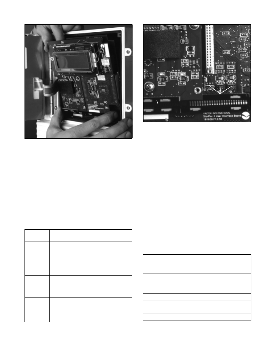
Figure 14: Replacing the Board Stack
Discrete Jumpers
Three sets of jumpers (Figure 15) are located on the
main circuit board underneath the personality module.
These jumpers are used to configure the operation of
discrete inputs and outputs. These are labeled Relay,
DI 1, and DI 2.
The relay jumper allows selection of normally open
(N.O.) and normally closed (N.C.) forms of the alarm
contacts (A-B=N.O. and B-C=N.C.). DI 1 and DI 2
allows selection of the input voltage range for the two
discrete input channels. (A-B=60-120V input range,
B-C=20-48V input range.)
Note: Both jumpers on each of these blocks must be
moved to the desired position for proper operation.
Caution: Do not apply high voltage when low
voltage sensing is selected. Damage will occur.
Figure 15: Discrete Jumpers Under
Personality Module
Discrete Jumpers
A
Table IV: Linear Actuator Mounting Kits
Actuator
Stroke
Spud
Mounting
Size
(inches)
(inches)
Kit
25
0.5 - 1.5
2.00
10007189
50
0.5 - 3
2.00
10062174
50
0.5 - 3
2.62
10007191
100
3
2.62 - 2.88
10007192
100
4
3.38 - 4.75
10007193
200
1 - 4
2.88
10054278
200
1.5 - 4
3.38 - 4.75
1005428
300
1 - 4
3.38 - 4.75
10054284
Mounting kit includes bracket, stem clamp, follower arm,
follower pin, and all necessary nuts, bolts and washers.
Table III: MaxFlo Rotary Actuator
Mounting Kits
Actuator
Shaft Size
Air To
Mounting
Size
Kit
25
0.4375
Open
10059457
25
0.4375
Close
10059457
25
0.625
Open
10059458
25
0.625
Close
10059458
25
0.875
Open
10059460
25
0.875
Close
10059460
50
0.875
Open
10059473
50
0.875
Close
10059472
50
1.125
Open
10059477
50
1.125
Close
10059476
100
1.5
Open
10059481
100
1.5
Close
10059480
200
1.5
Open
10094609
200
1.5
Close
10094608
Mounting kit includes bracket, linkage assembly, follower
arm,and all necessary nuts, bolts and washers.