Flowserve 2000 Series Digital Positioner User Manual
Page 12
42-12
Flowserve Corporation, Valtek Control Products, Tel. USA 801 489 8611
Driver Module Calibration
1. Hook power supply (24 VDC) leads to StarPac II /
Logix 2000 connector numbers 16 and 17.
2. Hook up supply pressure to the unit, using the port
marked S.
3. Remove the upper port plug from the Driver Mani-
fold and screw the pressure test fitting into the port.
4. Set the regulator pressure to 22 psig, plus or minus
0.5 psig by adjusting the set screw on the regulator
(refer to Figure 11).
5. Remove the test fitting and replace it with the port
plug ensuring that the seal washer is present.
6. Remove the lower port plug from the Driver Mani-
fold and screw the pressure test fitting into the port.
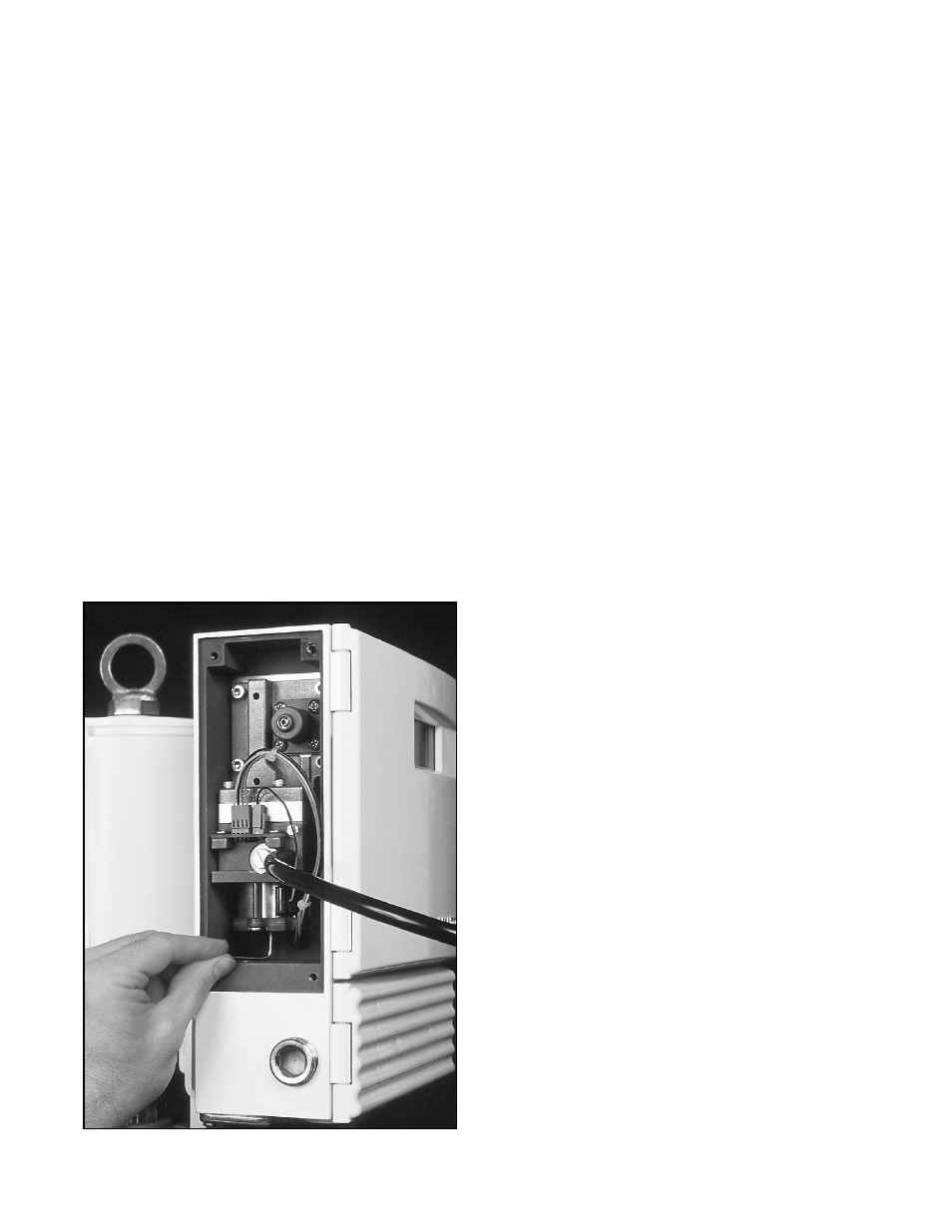
7. Set the Modulator pressure to 2 psig, plus or minus
0.25 psig by adjusting the set screw on the bottom
of the modulator cap (refer to Figure 13).
8. Remove the test fitting and replace it with the port
plug, making sure the seal washer is present.
9. Proceed with the positioner calibration routine. First,
edit register 40157 to put in a value of 2750 for the
null adjust. The valve should be set to be 50 percent
open during these calibrations and adjustments.
This typically takes several minutes to complete.
Replacing the Electronic Boards
The StarPac II / Logix 2000 has two main electronic
boards, one personality module, and one terminal strip
mounted inside the housing. The two boards are
located behind the keypad door of the housing, mounted
one atop the other in a stacked fashion. The personality
module is plugged into the lower right hand corner of the
boards.
If, after consulting with a local Valtek or factory repre-
sentative, and determination is made that the electronic
boards need replacement, proceed as follows.
1. Make sure the valve is by-passed or in a safe position.
Follow handling procedures that protect the boards
from the static electricity and ground currents.
2. To access the board stack, open the housing door.
Undo the two screws that fasten the keypad door to
the housing and swing out the keypad door (the
stacks will be visible). Because the factory places
a serial number on each stack, the board stack
should be kept together as one unit. Mixing boards
with other stacks is not recommended.
3. The top board consists of a main section and a
smaller, removable personality card on the lower
right corner. The size of this card is about two
square inches. The card contains the programming
logic and is sometimes removed for software cus-
tomizing. Remove the card by undoing the four
small screws holding it to the top board. Carefully
lift it out, as it is also held in place by a board-to-
board connector. Transport this card in a static
resistant pouch.
4. To install the personality card, align the board-to-
board connector and press straight in. Reinstall the
four screws. (Any time the version of the personal-
ity module is changed, re-initialize the system by
holding down the zero (0) button while turning the
24V power on – then releasing once the display is
legible. The unit will be in test mode and must be
reconfigured for proper operation.)
The Board Stack
1. Disconnect the power and air supply to the unit
before removing the electronic board stack. The
two pressurized pneumatic ports connect directly
with two board mounted pressure sensors. A total
of eight screws hold down the boards. The screw
with an allen head should not be removed. The
other seven are phillips head-type and can be
removed. Note that one of the seven phillips screws
is located on the lower right portion of lower board.
2. Undo the seven phillips screws and the board stack
will lift away from the housing. Disconnect the
connectors from the boards. Carefully undo the
integral clips as you pull the connector away from
the board (refer to Figure 14).
Figure 13: Setting Modulator Pressure