Figure 1: shielded wire diagram, Wiring and grounding guidelines, Installation valve installation – Flowserve 2000 Series Digital Positioner User Manual
Page 2
42-2
Flowserve Corporation, Valtek Control Products, Tel. USA 801 489 8611
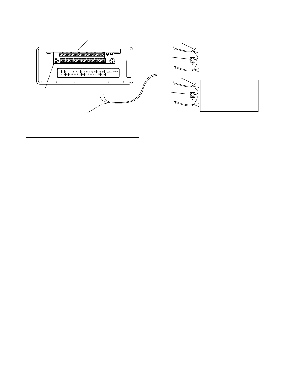
DCS
+ Analog Input
- Analog Input
+ Analog Output
- Analog Output
+ RS485
- RS485
+ 24V
- 24V
StarPac II User Interface Terminal
Grounding Screw for
Electrical Ground of Conduit
No Shield Connection at
StarPac II User Interface Terminal
Shields
Instrument
Ground
Shields
Instrument
Ground
AIB, Extender or
RS232/RS485 Converter
Figure 1: Shielded Wire Diagram
Preferred StarPac II / Logix 2000 Grounding
Tools required for StarPac II / Logix 2000
Maintenance and Start-up
1. Multi-meter w/alligator clips, probes & jumpers
2. 4-20 mA analog calibrator with power supply
3. RS-232-485 communication and cabling
4. Windows
TM
compatible PC
5. Standard 6-inch flat screwdriver
6. Standard phillips screwdriver
7.
1
/
4
-inch flat screwdriver
8. Small wire cutter (flush cut) & wire strippers
9. Needle-nose pliers
10.
1
/
16
-inch allen wrench
11. Vise grips
12. Small vise grips
13.
1
/
2
-inch nut driver
14.
5
/
32
-inch allen wrench
15. Large crescent wrench (minimum 15-inch)
16. 8-inch channel lock pliers
17.
3
/
32
-inch screwdriver
18. Wrist grounding strap
19. Antistatic bag or packaging
20. EPROM remover (PLCC type)
21. Electrical tape
22. Feedback shaft tool and drive module
pressure calibration connectors (supplied
with feedback module kit)
If the StarPac II is being installed in an insulated process
line, do not place more than four inches of insulation
around the pressure or temperature sensors; otherwise
the sensors may not operate properly. In addition,
NEVER insulate the unit electronics assembly or
remote-mounted temperature/pressure sensors (when
used).
CAUTION: Do not insulate the StarPac II / Logix
2000 electronics housing or remote-mounted pres-
sure or temperature sensors; otherwise excessive
heat may build up and affect operation.
Wiring and Grounding Guidelines
This section will help you achieve a maximum “noise -free”
environment and performance with a StarPac II / Logix
2000 unit.
Shielding Versus Grounding
All signals to the StarPac II / Logix 2000 unit should be
in shielded cables. Shields must be tied to a ground at
only one end of the cable to provide a place for environ-
mental electrical noise to be removed from the cable. A
ground wire (unlike a shield) is attached at both ends to
provide a continuous path for electrical conductivity.
Grounding Screw
The green grounding screw by the user interface termi-
nal block should be used to provide the unit with an
adequate and reliable earth ground reference. This
ground should be tied to the same ground as the
electrical conduit. Additionally, the electrical conduit
connecting to the unit should be earth grounded at both
ends of its run.
The green grounding screw must not be
used to terminate signal shield wires.
24VDC Power
The 24 VDC connection points will work best with
shielded twisted pair wire with the shield wire connected
INSTALLATION
Valve Installation
The StarPac II / Logix 2000 Intelligent Control System
valve is installed in the same manner as a conventional
control valve and according to industry standards. Refer
to the appropriate valve installation, operation, mainte-
nance instructions for proper installation procedures.