3 actuator mounting – Flowserve L120-85 Actuator User Manual
Page 12
NOTE: If your unit incorporates a rising stem application, it may be
shipped with a plastic cap over the Drive Sleeve Housing. If so, in
order to store without possible corrosion occurring, install a pipe
plug or protective stem cover to protect the Drive Sleeve Housing.
NOTE: Failure to comply with recommended storage procedures
could cause the warranty to be voided. For long-term storage proce-
dures, consult the Limitorque Customer Service Department.
4.3 Actuator Mounting
Your L120-85 is designed to perform actuation for torque only
applications (drive 1) or for torque and thrust applications (drive
2). If you are using a torque only configuration, before installing on
the valve or other actuated device, you will need to verify that the
Torque Drive Nut (piece 95) is properly bored and keyed to fit your
valve stem. If you are using a torque and thrust configuration, you
will need to verify that the Thrust Base Drive Sleeve (piece 101) is
properly threaded to fit your threaded valve stem. Use the following
procedures to check for proper fit of the Torque Drive Nut or the
Thrust Base Drive Sleeve.
4.3.1 Torque Only Applications (Drive 1)
(Refer to Figure 27)
Remove the Torque Nut Retaining Ring (piece 98) and Torque Drive
Nut (piece 95) from actuator.
Figure 2: L120-85 Torque Drive Nut and Retaining Ring Details
#95 Torque
Drive Nut
#98 Torque Nut
Retaining Ring
A) If Torque Drive Nut has been bored and keywayed by supplier,
verify dimensions of keyway for proper compatibility with the
valve stem.
B) If Torque Drive Nut has not been bored and keywayed by sup-
plier, it is provided solid (blank) to allow customer to custom
bore and key up to the maximum permissible sizes as listed:
Table 2: Torque Drive Nut: Maximum Allowable Bore and Key Sizes
Key Type
Maximum Bore in. (mm)
Maximum Key in. (mm)
Rectangle
2.750 (69.85)
.625 x .4375 (20 x 12)
Square
2.625 (66.67)
.625 x .625 (20 x 20)
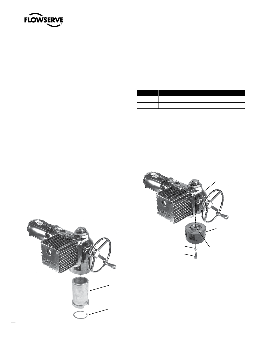
4.3.2 Torque and Thrust Applications
(Drive 2) (Refer to Figure 28)
Remove Socket Head Cap Screw (piece 110) and Lockwasher (piece
111) that holds the Thrust Base Housing Assembly to the actuator
Housing (piece 1).
Figure 3: Thrust Base removal from an L120-85
#111 Lockwasher
#110 Socket Head
Cap Screw
#100 Thrust Base
Housing
#1 Housing
#101 Thrust Base
Drive Sleeve
A) If the Thrust Base Drive Sleeve (piece 101) has been threaded by
supplier, verify thread compatibility with the threaded Valve Stem
by screwing Drive Sleeve onto the valve stem.
B) If Thrust Base Drive Sleeve (piece 101) has not been threaded by
supplier, it is provided solid (blank) to allow customer to custom
thread. Maximum threaded stem diameter is 3.25" (82.5 mm).
NOTE: If Thrust Base disassembly is required in order to thread
blank Thrust Base Drive Sleeve, remove Quad Rings (piece 107)
before removing Thrust Washer (piece 104) and Thrust Bearing
Limitorque L120-85 Installation, Operation and Maintenance FCD LMENIM1202-00 – 11/05
12