3 setting the potentiometer – Flowserve L120-85 Actuator User Manual
Page 22
4.7.3 Setting the Potentiometer
If your L120-85 actuator includes a Feedback Potentiometer supplied
for remote valve position indication, use an ohmmeter to calibrate
the position of the Potentiometer. Typically, the Potentiometer Spur
Gear is shipped from the factory dis-engaged from the Potentiom-
eter Drive Gear. If your supplier has not re-engaged and calibrated
the Potentiometer, use the following procedure to complete the
Potentiometer setup.
c
WARNING: Hazardous Voltage. Turn power OFF before
opening the Electrical Compartment Cover or calibrat-
ing the Feedback Potentiometer. Use extreme caution if
power is ON and the Electrical Compartment is OPEN.
1. Turn all power to the actuator OFF.
2. Using the Handwheel, position the actuator to mid-travel (valve
at the 50% position).
3. Disconnect the Potentiometer Wiring Harness from the Intercon-
nect Board or Terminal Strip.
4. Using an ohmmeter, verify that the potentiometer is in mid-
travel. The resistance from each End Connection to the Center
Connection should be half of the full resistance of the Poten-
tiometer. Example: a 1000 ohm potentiometer should read
approximately 500 ohms from one of the End Connections to the
Center Connection. If the reading is not correct, proceed to step
5. If the reading is correct proceed to step 11.
Figure 15: Potentiometer Calibration configuration
Pot Lead
End Connection
Pot Lead
Center Connection
Ohmmeter
5. If the Potentiometer Assembly is engaged with the Potentiom-
eter Drive Gear: Loosen the Hex Head Retaining Nut at the base
of the Potentiometer Bracket and dis-engage the Spur Gear from
the Potentiometer Drive Gear. This will allow manual rotation of
the Potentiometer Spur Gear. Continue to step 7.
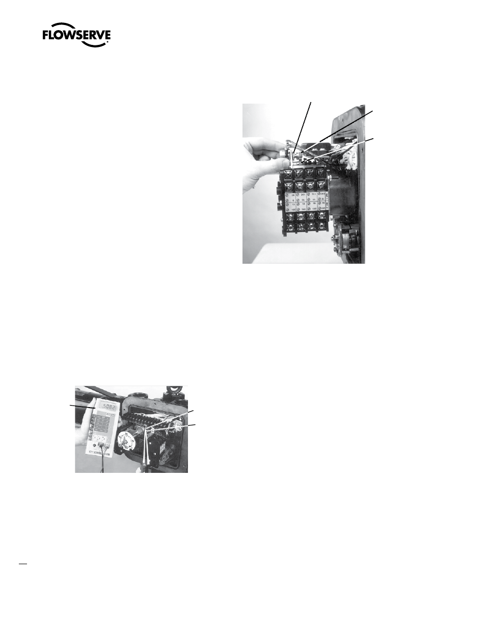
Figure 16: Loosening Potentiometer Assembly
Hex Head
Retaining Nut
Pontentiometer
Spur Gear
Pontentiometer
Drive Gear
6. If the Potentiometer Spur Gear is not engaged with the Potenti-
ometer Drive Gear continue to step 7.
7. Rotate the Potentiometer Spur Gear until the correct readings
are obtained as described in step 3.
8. Carefully reposition the Potentiometer Spur Gear to re-engage
with the gear train.
9. Re-tighten Hex Head Retaining Nut at the base of the Potentiom-
eter Bracket.
10. Recheck ohmmeter reading to assure Potentiometer adjustment
was not changed when Potentiometer was tightened to Potenti-
ometer Bracket. If Potentiometer setting is not accurate, repeat
steps 5–9. If ohmmeter reading is accurate, proceed to step 11.
11. Disconnect the ohmmeter and reconnect the Potentiometer wir-
ing to the Interconnect Board or Terminal Strip.
Limitorque L120-85 Installation, Operation and Maintenance FCD LMENIM1202-00 – 11/05
22