Start, operation, alarm and test, Nrs 1-40.1 – Flowserve NRS1-40.1 User Manual
Page 19
19
Start, Operation, Alarm and Test
NRS 1-40.1
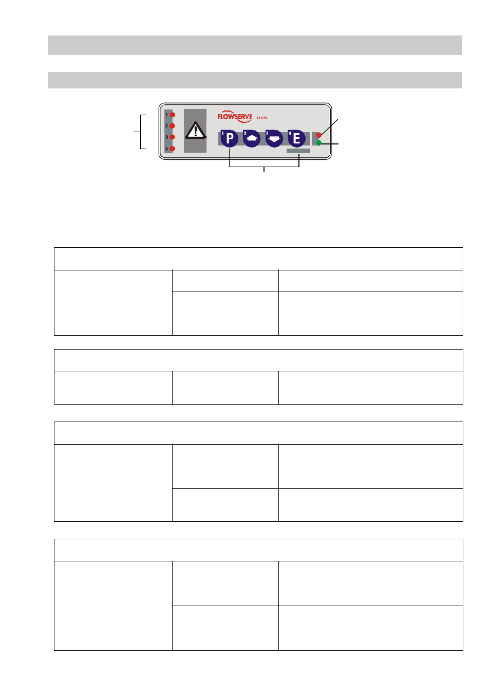
Assignment of signal LED / key / equipment
LED 1 / Key 1: Limiter 1 (e. g. level electrode NRG 1x-40, low level LW)
LED 2 / Key 2: Limiter 2 (e. g. level electrode NRG 1x-40, low level LW)
LED 3 / Key 3: Limiter 3 (e. g. level electrode NRG 1x-41.1, high level HW)
LED 4 / Key 4: Limiter 4 (e. g. temperature transmitter TRV 5-40, MAX temperature)
Start
Apply mains voltage.
LED "Power" is illuminated Mains voltage applied
LED 1– 4 are flashing
System is being started and tested.
Output contacts are open. Signalling output is
closing (lamp test).
Operation
Limiters 1– 4 indicate
no alarm
LED 1– 4
are not illuminated
Output contacts are closed,
signalling output is open.
Alarm
Limiters 1– 4,
one or more limiters
indicate an alarm
One or more of the LEDs
1, 2, 3, 4 are flashing
rapidly
De-energizing initiated,
signalling output is closed instantaneously.
One or more of the LEDs
1, 2, 3, 4 are illuminated
De-energizing period has elapsed, output
contacts are open, signalling output closed.
Test - Limiters 1 – 4
During operation:
Press key 1, 2, 3 or 4 and
hold it down until the end of
the test, limiters must react
as if there was an alarm.
LED 1, 2, 3 or 4
is flashing rapidly
Alarm simulated in limiter 1 - 4.
de-energizing initiated,
signalling output is closed instantaneously.
LED 1, 2, 3 or 4
is illuminated
De-energizing period has elapsed, output
contacts are open, signalling output closed.
Test finished.
GESTRA
NRS 1-40
GESTRA
NRS 1-40.1
TEST
Signal
LED
Malfunction alarm control unit
and bus status LED
Mains supply LED
Control keys
L 1
L 2
L 3
L 4
Fig. 7